
Handheld rapid and safe positioning cutting machine

A safe positioning and hand-held technology, which is applied in the direction of metal sawing equipment, sawing machine tools, metal processing equipment, etc., can solve the problems of inconvenient rapid positioning and stable use of cutting machines, difficult to clean up chip accumulation, and threats to user safety. , to achieve the effect of smooth and flexible rotation, convenient cutting work and easy cleaning

Inactive Publication Date: 2018-12-25
冯志超
View PDF0 Cites 2 Cited by
  • Summary
  • Abstract
  • Description
  • Claims
  • Application Information

AI Technical Summary

Problems solved by technology

[0003] The purpose of the present invention is to provide a hand-held fast and safe positioning cutting machine to solve the existing hand-held cutting machine proposed in the above background technology. In actual use, the problem of its own gravity needs to be considered, that is, there are It is very obvious that it is not easy to hold. At the same time, when a general cutting machine is cutting, its cutting effect depends entirely on the grasp of the person when holding it. Fast positioning and stable use. During the cutting process, the cutting waste will pop out due to the action of the rotating centrifuge, which poses a threat to the safety of the user. Similarly, the accumulation of chips is difficult to clean, and there is also a big problem for the cutting process. The problem of hindering the influence of

Method used


Image

  • Handheld rapid and safe positioning cutting machine
  • Handheld rapid and safe positioning cutting machine
  • Handheld rapid and safe positioning cutting machine

Examples


Embodiment Construction

[0028] The following will clearly and completely describe the technical solutions in the embodiments of the present invention with reference to the accompanying drawings in the embodiments of the present invention. Obviously, the described embodiments are only some, not all, embodiments of the present invention. Based on the embodiments of the present invention, all other embodiments obtained by persons of ordinary skill in the art without making creative efforts belong to the protection scope of the present invention.

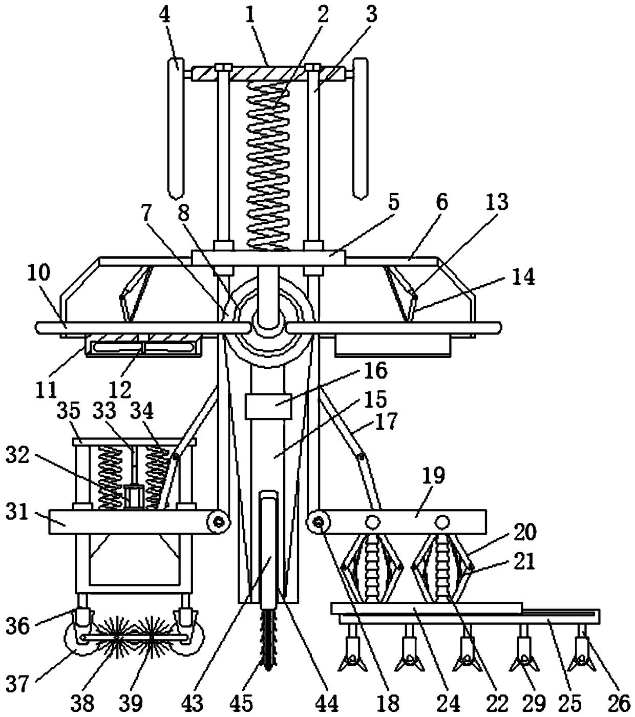
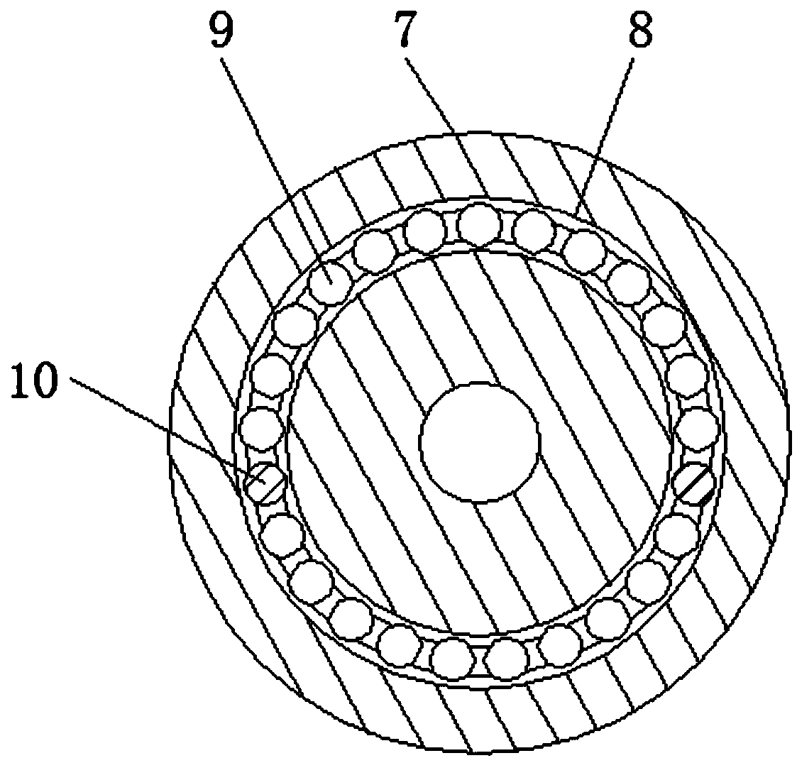
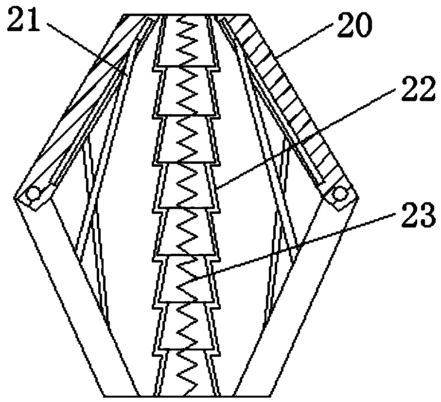
[0029] see Figure 1-7, the present invention provides a technical solution: a hand-held fast and safe positioning cutting machine, including a base plate 1 and a knife holder 15, a damping spring 2 is installed under the base plate 1, and the left and right sides of the damping spring 2 are provided with Screw 3, handles 4 are installed on the left and right sides of the base plate 1, a support plate 5 is arranged under the screw 3, and a cover 6 is fixed on ...


PUM


Abstract

The invention discloses a handheld rapid and safe positioning cutting machine. The handheld rapid and safe positioning cutting machine comprises a base plate and a knife rest; a damping spring is arranged below the base plate; screw rods are arranged on the left side and the right side of the damping spring; handles are arranged on the left side and the right side of the base plate; a supporting platform plate is arranged below the screw rods; a blocking cover is fixed on the side surface of the supporting platform plate; a ring disk is arranged below the supporting platform plate; a ring groove is formed in the surface of the ring disk; a motor port is fixed above the surface of the knife rest; and the knife rest is positioned below the ring disk. According to the handheld rapid and safepositioning cutting machine, the damping spring is provided, the vibration action force of people holding the handles can be relieved; through the screw rods, the handholding height of the whole device can be adjusted and stress is facilitated; a wind dissipating plate can perform angle rotation under the action of the ring groove on the ring disk; through combination of the traction effect of a telescopic pull rod and an inclined strut pull rod, good traction and support are obtained; and roll balls are used for enabling the wind dissipating plate to rotate on the ring disk stably and flexibly.

Description

technical field [0001] The invention relates to the technical field of cutting machines, in particular to a hand-held fast and safe positioning cutting machine. Background technique [0002] Cutting machine is a very common mechanical processing equipment. It mainly uses cutting and cutting means to change the shape of the product so that the product conforms to the size of the drawing. The cutting machine is divided into flame cutting machine, plasma cutting machine, laser cutting machine, water cutting, etc., laser cutting machine For the fastest efficiency, the highest cutting precision, the cutting thickness is generally small, the cutting speed of the plasma cutting machine is also very fast, and the cutting surface has a certain slope. The fastest, the highest cutting precision, and the cutting thickness is generally small. However, in the actual use of the existing hand-held cutting machines, it is necessary to consider the problem of its own gravity, that is, there ...

Claims


Application Information

Patent Timeline
Patent Type & Authority Applications(China)
IPC IPC(8): B23D61/02
CPCB23D61/02
Inventor 冯志超
Owner 冯志超
Learn More