Server overload control method and system

An overload control and server technology, applied in the field of network communication, which can solve the problems of delay, loss of response messages, and sharp increase in the request volume of proxy server 2

Active Publication Date: 2018-12-25
CHINANETCENT TECH
View PDF9 Cites 2 Cited by
  • Summary
  • Abstract
  • Description
  • Claims
  • Application Information

AI Technical Summary

Problems solved by technology

The reason for requesting message timeout retransmission may also be that the response message is lost or delayed during network transmission due to network jitter
like figure 2 As shown, the response code returned by proxy server 2 to proxy server 1 is 100 Trying resp

Method used


Image

  • Server overload control method and system
  • Server overload control method and system
  • Server overload control method and system

Examples


Embodiment Construction

[0060] The technical solutions in the embodiments of the present invention will be clearly and completely described below in conjunction with the accompanying drawings. Apparently, the described embodiments are only some, not all, embodiments of the present invention. Based on the embodiments of the present invention, all other embodiments obtained by persons of ordinary skill in the art without creative efforts fall within the protection scope of the present invention.

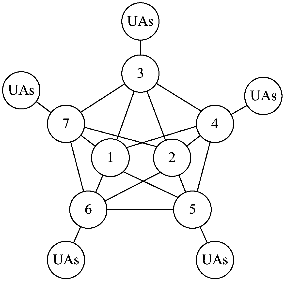
[0061] The server overload control method provided by the embodiment of the present invention can be used to control the server load in the SIP network, and the SIP network usually includes multiple SIP cluster systems. image 3 Shown is the SIP network topology diagram, it should be noted that, image 3 Shown is only part of a SIP network. The SIP network includes a communication path, multiple user agents (User Agents, UAs), and multiple servers on the communication path. image 3 The UAs shown represent ...


PUM


Abstract

The embodiment of the invention provides a server overload control method. The method comprises the following steps: a client calculates and stores the first time data of each historical transaction;the server calculates the second time data of each of the historical transactions and sends the second time data to the client; the client calculates a timeout reference time length of the current transaction according to each of the first time data and each of the second time data in a preset period; the client end calculates the transaction timeout length of the current transaction according tothe timeout reference length of the current transaction; the client controls the state of the current transaction according to the transaction timeout length of the current transaction. The inventionalso provides a server overload control system. The server overload control method and the server overload control system provided by the invention can solve the problem of server overload.

Description

technical field [0001] The invention relates to the technical field of network communication, in particular to a server overload control method and system. Background technique [0002] In the process of establishing a session through the Session Initiation Protocol (Session Initiation Protocol, SIP), if there is no congestion at the server on the communication path, usually the SIP session establishment process is as follows: figure 1 As shown: the user agent client (User Agent Client, UAC) first sends the INVITE request message to the user agent server (User Agent Server, UAS), and the UAC sends the INVITE request message through the proxy server 1 and the proxy server 2 (hereinafter collectively referred to as the proxy server) The message is routed and forwarded to the UAS. After receiving the request message, the UAS replies with response codes of 100Trying, 180Ringing, and 200OK in turn, and sends them to the UAC through the proxy server. [0003] The UAC determines t...

Claims


Application Information

Patent Timeline
IPC IPC(8): H04L12/801H04L29/08H04L29/06
CPCH04L47/12H04L65/1104H04L67/60
Inventor 庄伟胤
Owner CHINANETCENT TECH
Why Eureka
Try Eureka