
A switch that facilitates heat dissipation

A switch and cooling hole technology, applied in the field of network communication, can solve the problems of unstable interface connection, high maintenance rate, affecting normal use, etc., to achieve the effect of ensuring safe and normal operation and heat dissipation effect

Inactive Publication Date: 2018-12-25
明光顺和自动化设备科技有限公司
View PDF4 Cites 6 Cited by
  • Summary
  • Abstract
  • Description
  • Claims
  • Application Information

AI Technical Summary

Problems solved by technology

With the popularization of the network, the application of the switch is getting higher and higher, and the performance requirements of the switch are also getting higher and higher. The more powerful the function of the switch, the more ports, the more serious the accompanying heat problem of the switch. The traditional way of cooling only by heat sinks can no longer effectively solve the problem of serious heat generation in the switch. The accumulation of a large amount of heat will make the switch stay in high temperature for a long time. High temperature will reduce the stability and reliability of the circuit board and cause the interface The connection is unstable, and in severe cases, the circuit board will be damaged, affecting normal use, and the maintenance rate is high, and the service life is also affected

Method used


Image

  • A switch that facilitates heat dissipation
  • A switch that facilitates heat dissipation

Examples


Embodiment Construction

[0020] The following will clearly and completely describe the technical solutions in the embodiments of the present invention with reference to the accompanying drawings in the embodiments of the present invention. Obviously, the described embodiments are only some, not all, embodiments of the present invention. All other embodiments obtained by persons of ordinary skill in the art based on the embodiments of the present invention belong to the protection scope of the present invention.

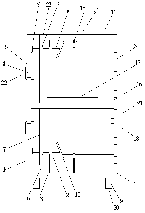
[0021] According to an embodiment of the present invention, a switch that facilitates heat dissipation is provided.

[0022] Such as Figure 1-2 As shown, the switch for heat dissipation according to the embodiment of the present invention includes a switch body 1, wherein a side plate 2 is provided on one side of the switch body 1, and a number of cooling holes 3 are uniformly arranged on the side plate 2, so that The other side of the switch body 1 is provided with a plurality of through h...


PUM


Abstract

The invention discloses a heat-dissipating switch which is convenient to dissipate heat, including the switch body, one side of the switch body is provided with a side plate, a plurality of heat dissipation holes are uniformly formed in the side plates, at the other side of the switch body, a heat dissipation fan is arranged on the inner side of the through hole, a motor is arranged at the bottomend of the switch body,at one end of that output shaft of the motor away from the motor is provide a worm, the worm is symmetrically provided with a set of turbines on one side, at the middle positionof the turbine, at one end of that rotate shaft, a movable lever is arranged on one side of the rotary table away from the rotary shaft, one end of the movable lever away from the rotary table is connected with the inner wall of the exchange body, a bearing is sleeved on the rotary shaft and located between the turbine and the rotary table, a fixed lever is arranged on one side of the bearing andmatched with the inner wall of the exchange body, and a sliding sleeve is sleeved on the movable lever and located between the rotary table and the side plate. The utility model has the advantages ofensuring the heat dissipation effect of the exchanger and ensuring the safe and normal operation of electronic components inside the exchanger.

Description

technical field [0001] The invention relates to the technical field of network communication, in particular to a switch that is convenient for heat dissipation. Background technique [0002] A switch is a data exchange device used in the communication field, which can provide an exclusive electrical signal path for any two network nodes connected to the switch. With the popularization of the network, the application of the switch is getting higher and higher, and the performance requirements of the switch are also getting higher and higher. The more powerful the function of the switch, the more ports, the more serious the accompanying heat problem of the switch. The traditional way of cooling only by heat sinks can no longer effectively solve the problem of serious heat generation in the switch. The accumulation of a large amount of heat will make the switch stay in high temperature for a long time. High temperature will reduce the stability and reliability of the circuit ...

Claims


Application Information

Patent Timeline
Patent Type & Authority Applications(China)
IPC IPC(8): H04L12/931H04Q1/02H05K7/20
CPCH04L49/40H04Q1/035H05K7/20136
Inventor 赵波
Owner 明光顺和自动化设备科技有限公司
Learn More