Display panel and display device

A technology of display panel and display area, applied in nonlinear optics, instruments, optics, etc., can solve the problem of low screen ratio and achieve the effect of increasing screen ratio

Inactive Publication Date: 2018-12-28
XIAMEN TIANMA MICRO ELECTRONICS
View PDF24 Cites 45 Cited by
  • Summary
  • Abstract
  • Description
  • Claims
  • Application Information

AI Technical Summary

Problems solved by technology

[0004] Embodiments of the present invention provide a display panel and a display device, which are used to solve t

Method used


Image

  • Display panel and display device
  • Display panel and display device
  • Display panel and display device

Examples


Embodiment Construction

[0046] In order to make the purpose, technical solutions and advantages of the present invention more clear, the following will clearly and completely describe the technical solutions in the embodiments of the present invention with reference to the drawings in the embodiments of the present invention.

[0047] In addition to compressing the upper and lower non-display areas of the mobile phone and the full-screen design of the "notch" represented by the iPhone X, at present, the iPhone X is also gradually moving towards a full-screen design without "notch", for example, setting the photosensitive components such as the camera in the display area Full screen in .

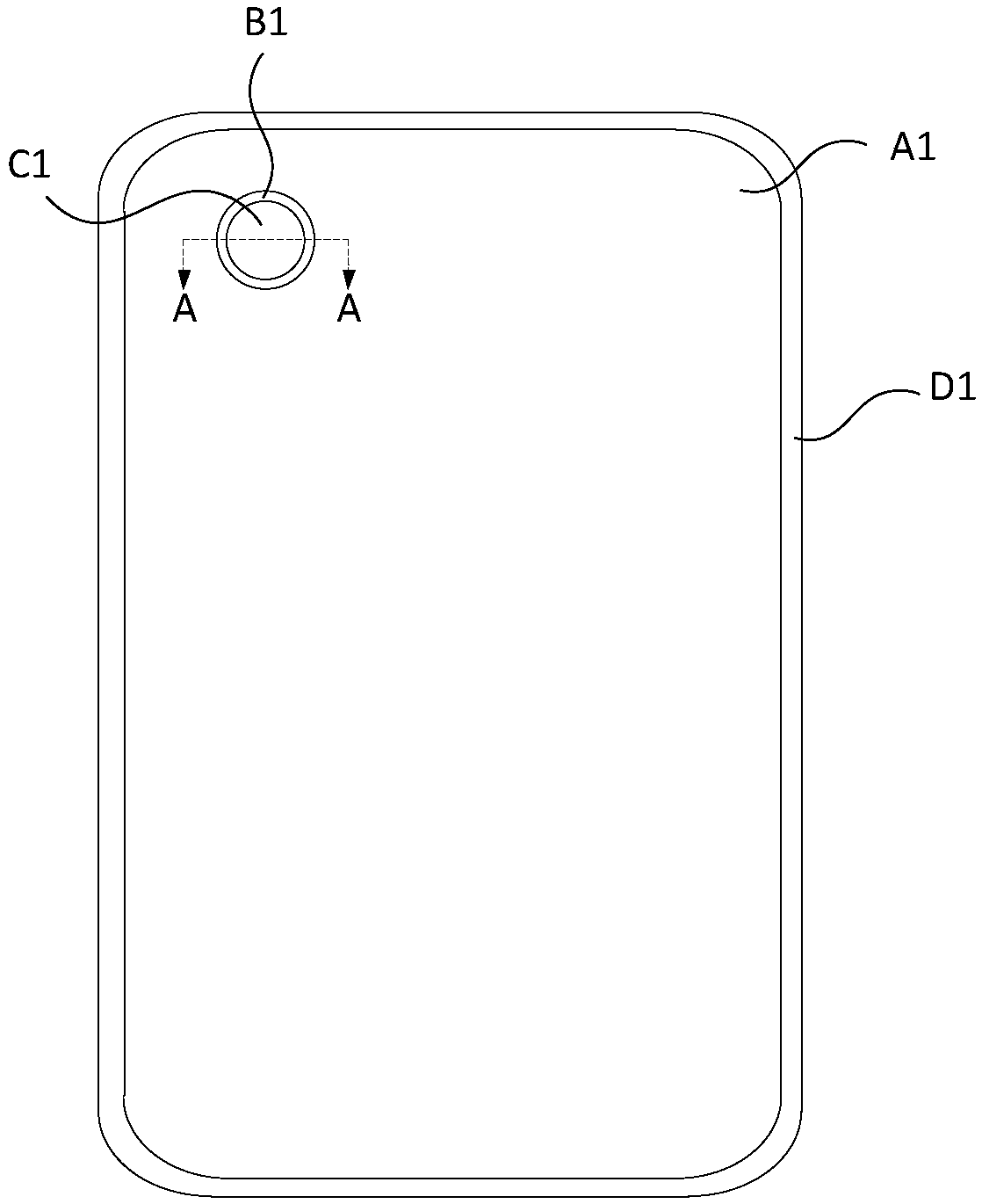
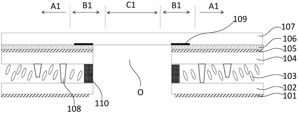
[0048] For a full screen with photosensitive components such as a camera installed in the display area, such as figure 1 As shown, it is a top view of a display panel in which holes are designed for the film layer of the display panel at the corresponding positions of the photosensitive components such as the camera...


PUM


Abstract

The invention discloses a display panel and a display device, which are used for solving the technical problem that the display panel in the prior art has a low screen-to-body ratio due to boring. Wherein the display panel includes: a light transmitting area, a display area, and a first non-display area. The display area surrounds the light transmitting area, and the first non-display area surrounds the display area. The display panel includes a first substrate and a second substrate disposed opposite to each other; a first support portion and a first liquid crystal layer are disposed betweenthe first substrate and the second substrate in the display area; a plurality of color filter film blocks are disposed on one side of the second substrate adjacent to the first substrate; a black matrix is disposed between each of the color filter film blocks; in the light transmitting area, at least one convex structure is disposed on the side of the second substrate adjacent to the first substrate.

Description

technical field [0001] The present invention relates to the field of display technology, in particular to a display panel and a display device. Background technique [0002] At present, display panels with full-screen design are more and more popular among consumers because of their high screen-to-body ratio. Full-screen displays usually adopt ultra-narrow bezel design around them, and set a light-transmitting area in the display area (Active Area, AA). This light-transmitting area is used for placement of components such as cameras and earpieces. [0003] In the light-transmitting area, the film layer of the display panel may need to dig holes, and place the camera, earpiece and other components at the corresponding positions of the holes. In order to fix the film layer after the hole is dug, a plastic frame is usually set at the hole dug, that is, there is a frame around the hole. However, since the frame glue is opaque, it blocks light, resulting in a reduction in the a...

Claims


Application Information

Patent Timeline
IPC IPC(8): G02F1/1339G02F1/1333
CPCG02F1/1333G02F1/13394
Inventor 黄懿兵王海亮任玮卢丽君杨雁郑斌义吴玲沈柏平
Owner XIAMEN TIANMA MICRO ELECTRONICS
Why Eureka
Try Eureka