Narrow frame display panel, manufacturing method thereof and display device

A display panel and display device technology, applied in the direction of static indicators, final product manufacturing, sustainable manufacturing/processing, etc., can solve the problems affecting the narrow frame of the display, improve assembly accuracy, reduce frame width, and improve screen The effect of proportion

Inactive Publication Date: 2018-01-16
WUHAN CHINA STAR OPTOELECTRONICS TECH CO LTD
View PDF5 Cites 34 Cited by
  • Summary
  • Abstract
  • Description
  • Claims
  • Application Information

AI Technical Summary

Problems solved by technology

[0004] However, in a general display using the COF scheme, the FPC is bound on the surface of the array substrate facing the opposite substrate, and the display needs to design a front frame to block the binding end. Although it plays an aesthetic role, it leads to the binding of the display. There is always a certain border width at the end, which affects the narrow border of the display

Method used


Image

  • Narrow frame display panel, manufacturing method thereof and display device
  • Narrow frame display panel, manufacturing method thereof and display device
  • Narrow frame display panel, manufacturing method thereof and display device

Examples


Embodiment Construction

[0026] In order to make the object, technical solution and advantages of the present invention more clear, the present invention will be further described in detail below in conjunction with the accompanying drawings and embodiments. It should be understood that the specific embodiments described here are only used to explain the present invention, not to limit the present invention.

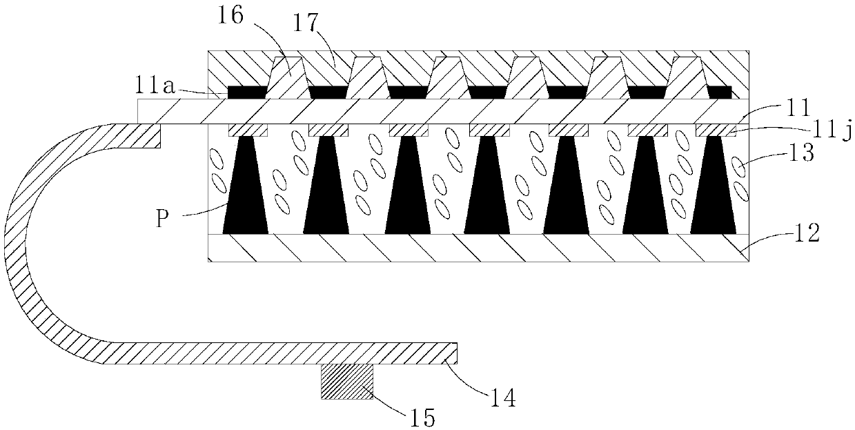
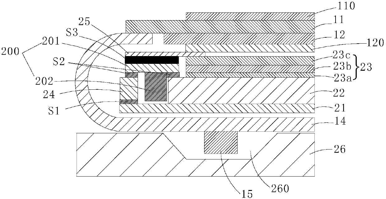
[0027] refer to figure 1 with figure 2 The narrow-frame display panel in the embodiment of the present invention mainly includes an array substrate 11, an opposite substrate 12, a liquid crystal 13 filled between the array substrate 11 and the opposite substrate 12, a flexible circuit board 14, and a driver chip 15. The array substrate 11 is located The side is the light-emitting surface, and the backlight enters light from the side where the opposite substrate 12 is located. One end of the array substrate 11 is a binding end, and one end of the flexible circuit board 14 is bound on the surfa...


PUM


Abstract

The invention discloses a narrow frame display panel and a manufacturing method thereof. The narrow frame display panel comprises an array substrate, a counter-direction substrate, liquid crystals, aflexible circuit board and a driving chip, wherein the part between the array substrate and the counter-direction substrate is filled with the liquid crystals, the side at which the array substrate ispositioned is a light emitting surface, and one end of the array substrate is a binding end; one end of flexible circuit board is bound to the surface, the binding end, which faces to the counter-direction substrate, and the other end of the flexible circuit is bound with the driving chip; the surface, facing to the counter-direction substrate, of the array substrate is provided with a metal filmlayer with hollow patterns, and a plurality of spacing pillars are convexly arranged on the surface, facing to the array substrate, of the counter-direction substrate, and extend to prop against themetal film layer. According to the display panel provided by the invention, the flexible circuit board cannot be seen from the outer side, so that the width of a narrow frame is narrowed, and the screen occupying ratio is increased; meanwhile, through the propping of the spacing pillars and the corresponding part of the hollow patterns of the metal film layer at the inner side of the array substrate, the assembly process of the substrates of the display panel can be realized by assistance, and the assembly precision is increased.

Description

technical field [0001] The present invention relates to the field of display technology, in particular to a narrow frame display panel, a manufacturing method thereof, and a display device. Background technique [0002] At present, the popularity of full-screen mobile phones is getting higher and higher, and screens with high screen-to-body ratios are becoming more and more popular. As a result, many narrow bezel solutions have been created, mainly for the left and right bezels, but for mobile phones, the lower bezels have always been improved to increase the screen-to-body ratio. It's a big issue. The so-called screen-to-body ratio refers to the ratio of the screen area to the overall machine area. A higher screen-to-body ratio can bring users a better visual experience. Flexible OLED displays are currently a key element for achieving hyperboloid designs. With the maturity of flexible OLED technology, more innovations and changes will inevitably occur in the appearance des...

Claims


Application Information

Patent Timeline
Patent Type & Authority Applications(China)
IPC IPC(8): G02F1/1333G02F1/133
CPCG02F1/13452G02F1/13394G02F1/136209G02F2201/50G02F2201/48H05K2201/10128H05K1/189Y02E10/549G02F1/133354G02F1/133562G02F1/136222Y02P70/50H10K77/111H10K50/86H10K71/00G02F1/133308G02F1/1345
Inventor 李得俊崔宏青宋文庆
Owner WUHAN CHINA STAR OPTOELECTRONICS TECH CO LTD
Why Eureka
Try Eureka