Amorphous magnetic core vertical winding inductor

A technology of inductors and magnetic cores, applied in the field of inductors, can solve the problems of smaller total contact area, poor consistency, and high processing costs, reduce the increase in magnetic core loss, improve consistency, yield, and EMC effects improved effect

Pending Publication Date: 2017-11-10
ADVANCED TECHNOLOGY & MATERIALS CO LTD
View PDF6 Cites 2 Cited by
  • Summary
  • Abstract
  • Description
  • Claims
  • Application Information

AI Technical Summary

Problems solved by technology

[0002] Fe-Si-B amorphous magnetic powder core is a preferred magnetic core material for inductors in switching power supplies and inverter power supplies because of its excellent soft magnetic properties such as low high-frequency loss and good anti-DC superposition characteristics, but the current market The amorphous magnetic powder cores used in the world are generally prepared by crushing Fe-Si-B amorphous strips, because the soft magnetic properties of Fe-Si-B amorphous alloys are very sensitive to stress, which leads to the impact of amorphous magnetic powder cores on coatings. Resin requirements are very high. In most cases, the core loss of the coated amorphous magnetic powder core is generally increased by about 20% compared with the uncoated amorphous magnetic powder core, and even higher than 30% in some extreme cases. , poor product consistency
In addition, in the process of preparing the inductor, due to the large number of winding turns, it will also generate stress on the coated amorphous magnetic powder core, thereby further increasing the core loss
And because the strength of the Fe-Si-B amorphous magnetic powder core is poor, a large number of defective products will be produced during the chamfering coating process, and the yield rate is low
In addition, the Fe-Si-B amorphous alloy has a large saturation magnetostriction coefficient, which causes the Fe-Si-B amorphous magnetic powder core to generate a lot of noise in some high-current applications, which affects the operation of the entire system. stability
[0003] At the same time, in order to effectively reduce the electromagnetic interference caused by the leakage magnetic field in the closed magnetic circuit of the high-frequency inductance and the eddy current loss caused by the leakage magnetic field of the winding, the existing magnetic powder core winding process generally uses round wires to be evenly and densely wound. Inductance requirements, the number of winding turns is between tens of turns and hundreds of turns. In addition, in order to obtain high inductance under high current, it is necessary to adopt the method of parallel connection of multiple round wires and multi-layer winding, so that it must Manual winding increases the difficulty of winding and high processing costs
And the use of multi-layer winding will inevitably increase the parasitic stray capacitance of the winding, which will bring a large peak to the current waveform and aggravate the electromagnetic interference
The dense stacking of round copper wires makes the total contact area between the conductor and the external air smaller, and surrounds the magnetic core, affecting the cooling effect of the inductor
Moreover, it is difficult to realize automatic winding for products with a high occupation rate of the inner hole of the magnetic ring, which affects the consistency of the product

Method used


Image

  • Amorphous magnetic core vertical winding inductor
  • Amorphous magnetic core vertical winding inductor
  • Amorphous magnetic core vertical winding inductor

Examples


Embodiment approach

[0039] A preferred embodiment of the preparation method of the above-mentioned amorphous magnetic core vertical winding inductor provided by the present invention includes the following steps:

[0040] In the step of cutting the annular amorphous magnetic core, the purchased or self-made annular amorphous magnetic core 20 is loaded into the tooling, and the magnetic core is cut into at least two magnetic core segments along the axial direction of the annular amorphous magnetic core 20; The core section can still be combined into a complete annular amorphous magnetic core after being put on the metal steel strip; in the preferred embodiment of the present invention, the method of cutting with a grinding wheel is adopted in this step, and the thickness of the selected grinding wheel cutting piece is preferably 0.1mm- 2mm, more preferably 0.5-1mm; if the grinding wheel is too thin, it is easy to break inside the magnetic powder core; if the grinding wheel is too thick, the loss of...

Embodiment 1

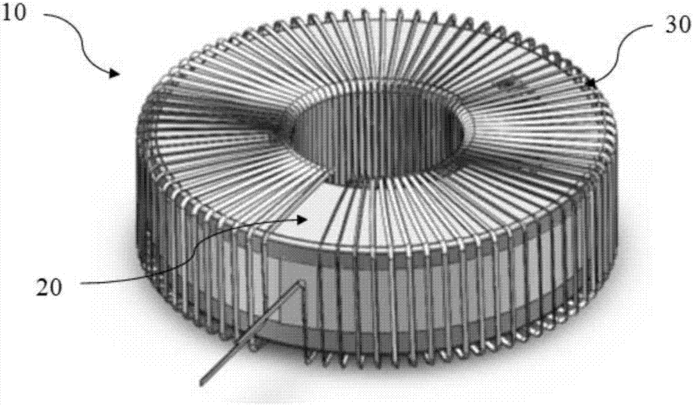
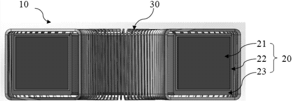
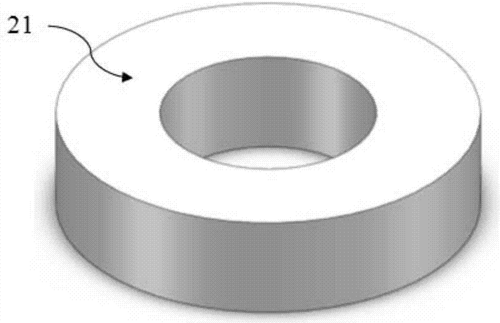
[0045] The vertically wound amorphous core inductor 10 of this embodiment is composed of an annular amorphous core 20 and a flat coil 30 , and the flat coil 30 is vertically wound on the annular amorphous core 20 with 85 turns. More specifically, the annular amorphous magnetic core 20 is Fe 78 Si 9 B 13 (The subscript number of the composition indicates the atomic percentage) The annular amorphous magnetic powder core 21 is put into a plastic sheath 23 and sealed and solidified with a silicone resin 23, and then cut into two magnetic core segments 24 and 25 by a grinding wheel and then combined, wherein, Each magnetic core segment 24, 25 is tightly bound into an annular whole by metal steel bands. figure 1 It is the overall effect diagram of the amorphous magnetic core vertical winding inductor of this embodiment; figure 2 It is a schematic cross-sectional view of the assembled amorphous core vertically wound inductor of this embodiment; image 3 For the Fe-Si-B annular a...

Embodiment 2

[0064] The preparation method of embodiment 2 is the same as that of embodiment 1, except that the number of turns of the vertically wound flat coil is 45 turns. Table 5 shows the inductance characteristic parameters of Embodiment 1 and Embodiment 2. It can be seen from the data in Table 4 that the number of turns decreases, and the inductance attenuation range at 10A is low. The inductance of 85 turns is attenuated to 73.3%, while the inductance of 45 turns is only Attenuation to 95.5%. In practical applications, according to the actual performance requirements, the smaller the number of turns, the better the anti-saturation capability under the condition of satisfying the requirements of the initial inductance performance.

[0065] Table 5 Comparison of installed inductance characteristics between embodiment 1 and embodiment 2

[0066]

[0067]


PUM

PropertyMeasurementUnit
thicknessaaaaaaaaaa
thicknessaaaaaaaaaa
widthaaaaaaaaaa

Abstract

The invention belongs to the field of inductors, and particularly relates to an amorphous magnetic core vertical winding inductor. The amorphous magnetic core vertical winding inductor comprises an annular amorphous magnetic core and a flat coil, wherein the annular amorphous magnetic core is uniformly and vertically wound with the flat coil; the annular amorphous magnetic core comprises a protection box and an iron-based amorphous magnetic powder core arranged in the protection box; spaces between opposite sides of the iron-based amorphous magnetic powder core and the protection box are filled with organic resin; the annular amorphous magnetic core is constructed by combining at least two magnetic core segments; the magnetic core segments can also be bound together through a metal steel belt; and non-magnetic gaps are formed between adjacent magnetic core segments. Through adoption of the amorphous magnetic core vertical winding inductor provided by the invention, relatively large noise generated by the amorphous magnetic powder core during working under large current can be lowered effectively; meanwhile, the heat-dissipation effect of the inductor and the EMC (Electro Magnetic Compatibility) effect of a circuit can be improved; and automatic winding of the inductor is realized.

Description

technical field [0001] The invention relates to the field of inductors, in particular to an amorphous magnetic core vertical winding inductor. Background technique [0002] Fe-Si-B amorphous magnetic powder core is a preferred magnetic core material for inductors in switching power supplies and inverter power supplies because of its excellent soft magnetic properties such as low high-frequency loss and good anti-DC superposition characteristics, but the current market The amorphous magnetic powder cores used in the world are generally prepared by crushing Fe-Si-B amorphous strips, because the soft magnetic properties of Fe-Si-B amorphous alloys are very sensitive to stress, which leads to the impact of amorphous magnetic powder cores on coatings. Resin requirements are very high. In most cases, the core loss of the coated amorphous magnetic powder core is generally increased by about 20% compared with the uncoated amorphous magnetic powder core, and even higher than 30% in s...

Claims


Application Information

Patent Timeline
Patent Type & Authority Applications(China)
IPC IPC(8): H01F27/08H01F27/255H01F27/28H01F27/33H01F27/34H01F41/00
CPCH01F27/08H01F27/255H01F27/2847H01F27/2876H01F27/2895H01F27/33H01F27/34H01F41/00H01F2027/2857
Inventor 王湘粤唐冬冬李广敏刘志坚刘天成李德仁卢志超
Owner ADVANCED TECHNOLOGY & MATERIALS CO LTD
Why Eureka
Try Eureka