

A rotatable environment-friendly photovoltaic power generation device
A photovoltaic power generation and environment-friendly technology, which is applied in the field of rotatable and environment-friendly photovoltaic power generation devices, can solve problems such as changes in the incident angle of light, impact on photovoltaic power generation efficiency, scrapping, etc., and achieve the effect of improving power generation efficiency
- Summary
- Abstract
- Description
- Claims
- Application Information
AI Technical Summary
Problems solved by technology
Method used
Image

Examples
specific Embodiment approach 1
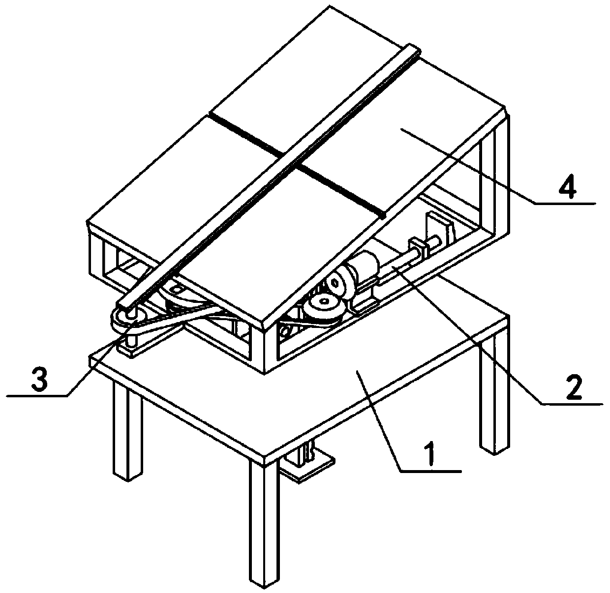
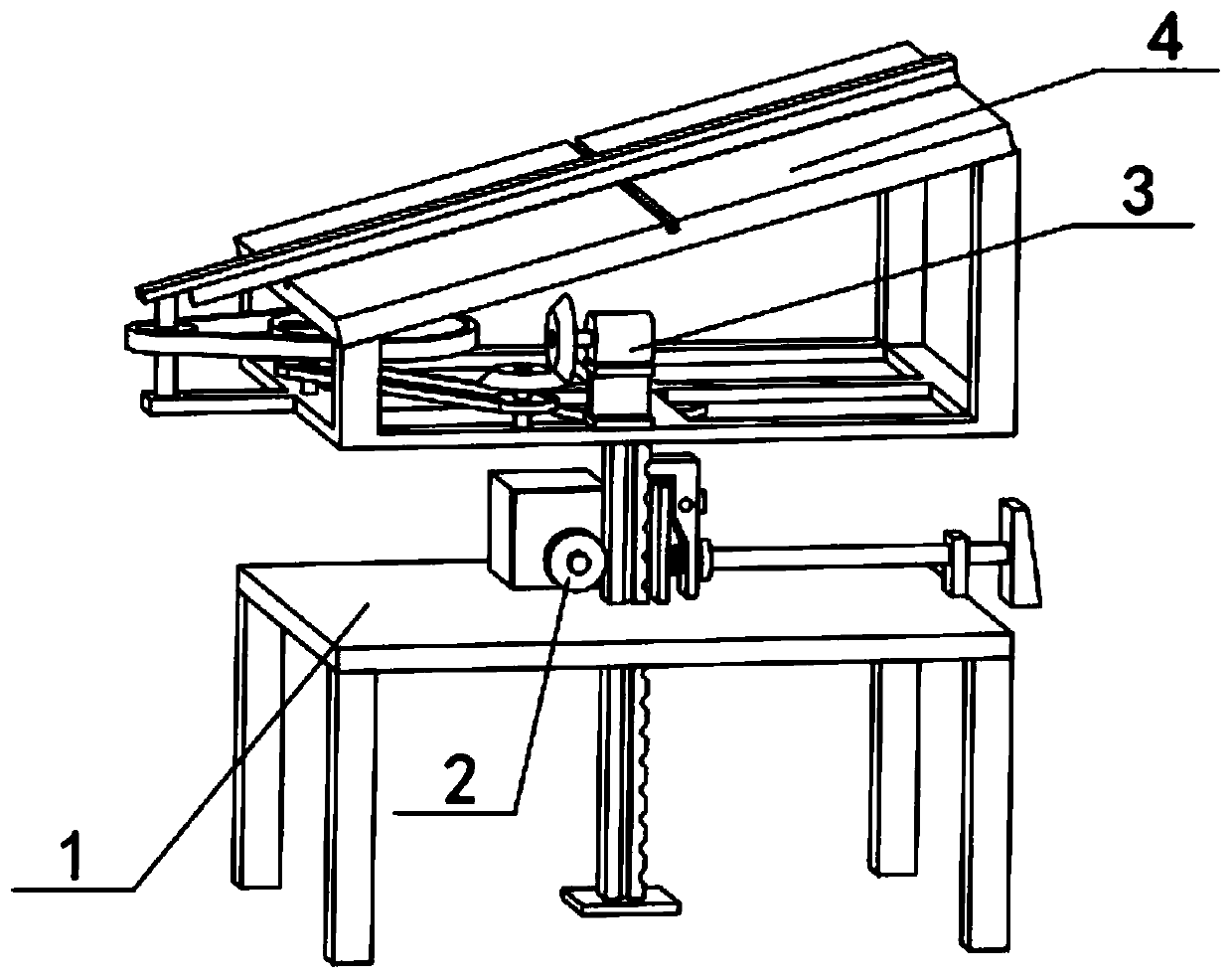
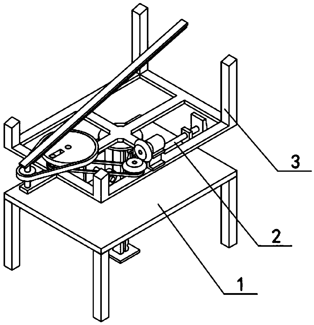
[0042] Combine below Figure 1-23 Describe this embodiment, a rotatable environment-friendly photovoltaic power generation device, including a base 1, a lifting mechanism 2, a cleaning mechanism 3, a photovoltaic power generation device 4 and a rotating mechanism 5, and the lifting mechanism 2 can be used to automatically lock the device after lifting the device High degree of action, so as to prevent the device from being soaked in water, perform periodic swinging motion through the cleaning mechanism 3, thereby cleaning the dust on the photovoltaic panel, and adjust the orientation of the photovoltaic power generation equipment through the rotation mechanism 5, so that the photovoltaic power generation equipment is more powerful towards the light intensity direction to improve power generation efficiency.
[0043] The base 1 includes a base body 1-1, a special rack groove 1-2, a waterproof casing 1-4 and a sealing cover 1-5, and the special rack groove 1-2 is arranged on the...
specific Embodiment approach 2
[0048] Combine below Figure 1-23 Describe this embodiment, this embodiment will further explain Embodiment 1, the auxiliary support seat 1-3, the auxiliary support seat 1-3 is fixedly connected to the middle side of the right end of the base body 1-1, the auxiliary support seat 1-3 There is brake lever 2-3-1 connected by key sliding, and brake lever 2-3-1 cannot rotate, so this key will be long enough to be more stable when brake lever 2-3-1 moves left and right.
specific Embodiment approach 3
[0050] Combine below Figure 1-23 Describe this embodiment, this embodiment will further explain Embodiment 2, the pedal 2-3-3 is fixedly connected to the right end of the brake lever 2-3-1, and the pedal 2-3-3 is located at the bottom of the auxiliary support seat 1-3. right end.
PUM
 Abstract
Description
Claims
Application Information