Multifunctional redwood sofa
A multi-functional, sofa technology, applied in chairs, stools, home appliances, etc., can solve the problems of non-adjustable backrest, no leg support structure, single structure, etc., to improve comfort, convenience, and strength. Effect
- Summary
- Abstract
- Description
- Claims
- Application Information
AI Technical Summary
Problems solved by technology
Method used
Image
Examples
specific Embodiment approach 1
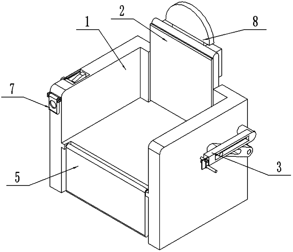
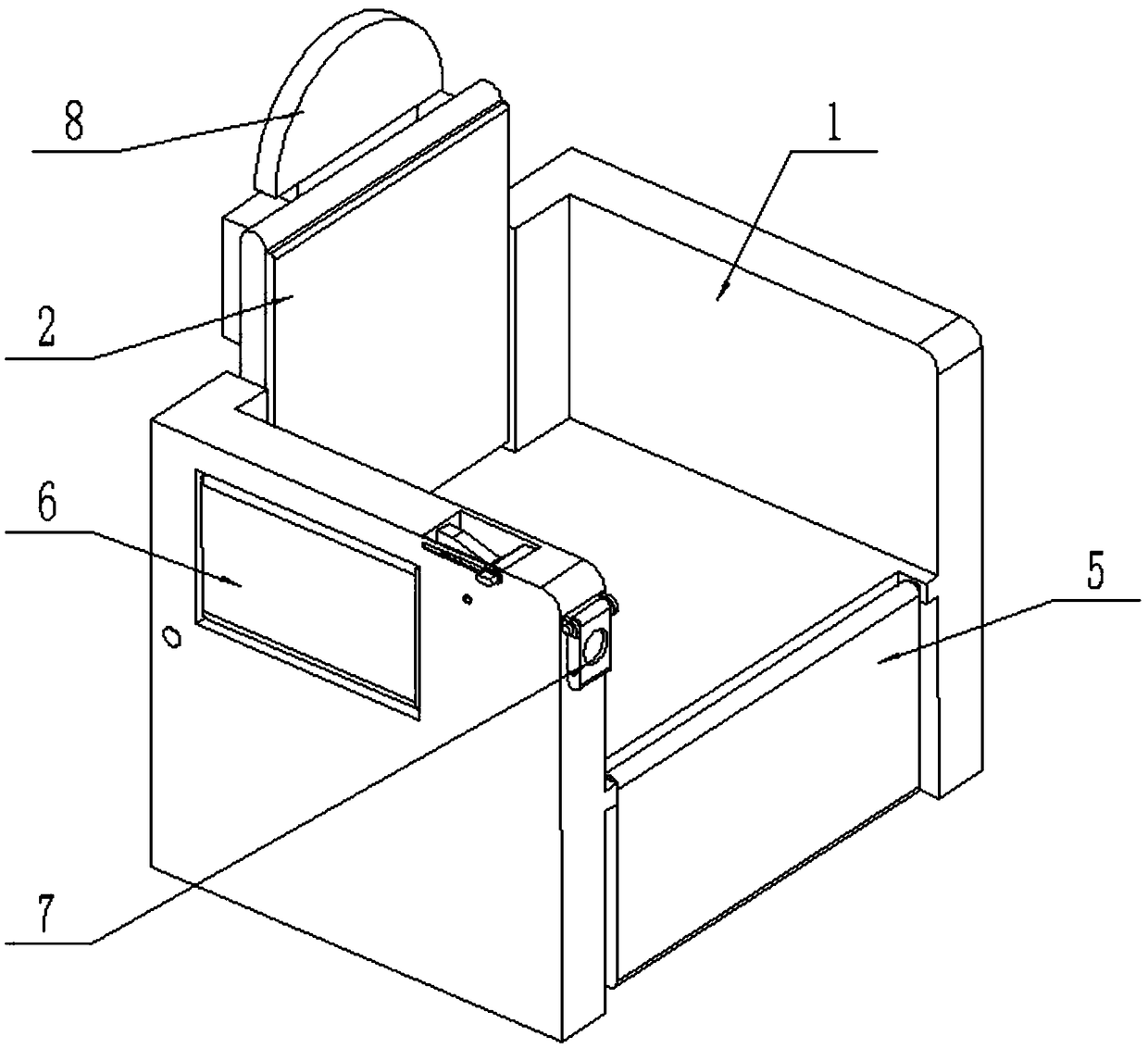
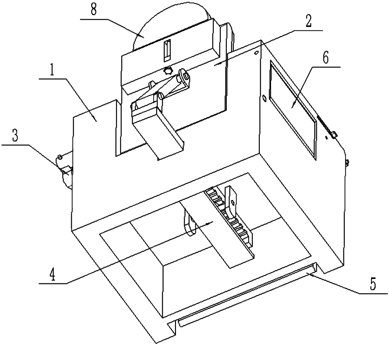
[0033] Such as Figure 1-13 As shown, a mahogany multifunctional sofa includes a sofa body 1, an adjustable backrest 2, a backrest adjustment assembly 3, a linkage assembly 4 and a leg support plate 5; the bottom end of the sofa body 1 is provided with a rectangular hollow groove 1- 1; the front end of the sofa body 1 is provided with a leg supporting plate groove 1-2 and a front rack chute 1-3, and the front rack chute 1-3 is connected to the leg supporting plate groove 1-2; the sofa The rear end of the body 1 is provided with a backrest groove 1-4 and a rear rack chute 1-5, and the rear rack chute 1-5 is located at the lower end of the backrest groove 1-4; the front rack chute 1-3, The rectangular hollow groove 1-1 communicates with the rear rack chute 1-5;
[0034] The lower end of the adjustable backrest 2 is rotatably connected to the lower end of the inner side of the backrest groove 1-4 through the first hinge shaft;
[0035] The backrest adjustment assembly 3 is fixedl...
specific Embodiment approach 2
[0038] Such as Figure 1-13 As shown, the backrest adjustment assembly 3 includes a hand rocker 3-1, a rotating connecting plate 3-2, a worm 3-3, a rod frame plate 3-4, a worm wheel 3-5, a screw 3-6, a rectangular frame 3- 7. The horizontal sliding column 3-8 and the chute arm 3-9; the axes of the worm gear 3-5 and the screw rod 3-6 are collinear and have axial positioning; the hand rocker 3-1 is fixedly connected to the rotating connecting plate 3 -2, the other end of the rotating connecting plate 3-2 is fixedly connected to one end of the worm screw 3-3, and the worm screw 3-3 is connected to the rod frame plate 3-4 through the rotation fit of the bearing with seat, and the rod frame plate 3-4 Fixedly connected to the front end of the rectangular frame 3-7; the worm 3-3 is meshed with the transmission connection worm wheel 3-5, the worm wheel 3-5 is fixedly connected to the front end of the screw 3-6, and the front and rear ends of the screw 3-6 are respectively rotated and ...
specific Embodiment approach 3
[0039] Such as Figure 1-13 As shown, the linkage assembly 4 includes an upper hinge seat 4-1, a push-pull arm 4-2, a lower hinge seat 4-3, a transmission rack 4-4, a first limit block 4-5, a first gear 4- 6. Wheel shaft 4-7, axle frame plate 4-8, passive rack 4-9, second limit block 4-10 and top block 4-11; the upper hinge seat 4-1 is fixedly connected to the adjustable backrest 2, the two ends of the push-pull arm 4-2 are respectively hinged on the upper hinge seat 4-1 and the lower hinge seat 4-3 through the hinge shaft; the lower hinge seat 4-3 is fixedly connected to the transmission rack 4 The rear end of -4, the middle end of the drive rack 4-4 is slidingly fitted and connected in the rear rack chute 1-5, and the lower side of the front end of the drive rack 4-4 is fixedly connected to the first limit block 4-5, The first limiting block 4-5 is located inside the rectangular hollow groove 1-1; the transmission rack 4-4 is meshed and connected to the first gear 4-6; the ...
PUM
 Abstract
Description
Claims
Application Information
 - R&D
- Intellectual Property
- Life Sciences
- Materials
- Tech Scout
- Unparalleled Data Quality
- Higher Quality Content
- 60% Fewer Hallucinations
Browse by: Latest US Patents, China's latest patents, Technical Efficacy Thesaurus, Application Domain, Technology Topic, Popular Technical Reports.
© 2025 PatSnap. All rights reserved.Legal|Privacy policy|Modern Slavery Act Transparency Statement|Sitemap|About US| Contact US: help@patsnap.com


