Camera mounting rack

A camera and mounting bracket technology, applied in the field of cameras, can solve the problems of providing support for rotation, difficult to meet installation requirements, and unable to adjust the camera at multiple angles.

Inactive Publication Date: 2019-01-04
泸州兴晨宇科技有限公司
View PDF0 Cites 4 Cited by
  • Summary
  • Abstract
  • Description
  • Claims
  • Application Information

AI Technical Summary

Problems solved by technology

In the face of these situations, because the current mounting frame cannot provide support for the multi-angle adjustment and rotation of

Method used


Image

  • Camera mounting rack
  • Camera mounting rack
  • Camera mounting rack

Examples


Embodiment Construction

[0021] The present invention will be further described in detail below in conjunction with specific examples, but the implementation of the present invention is not limited thereto.

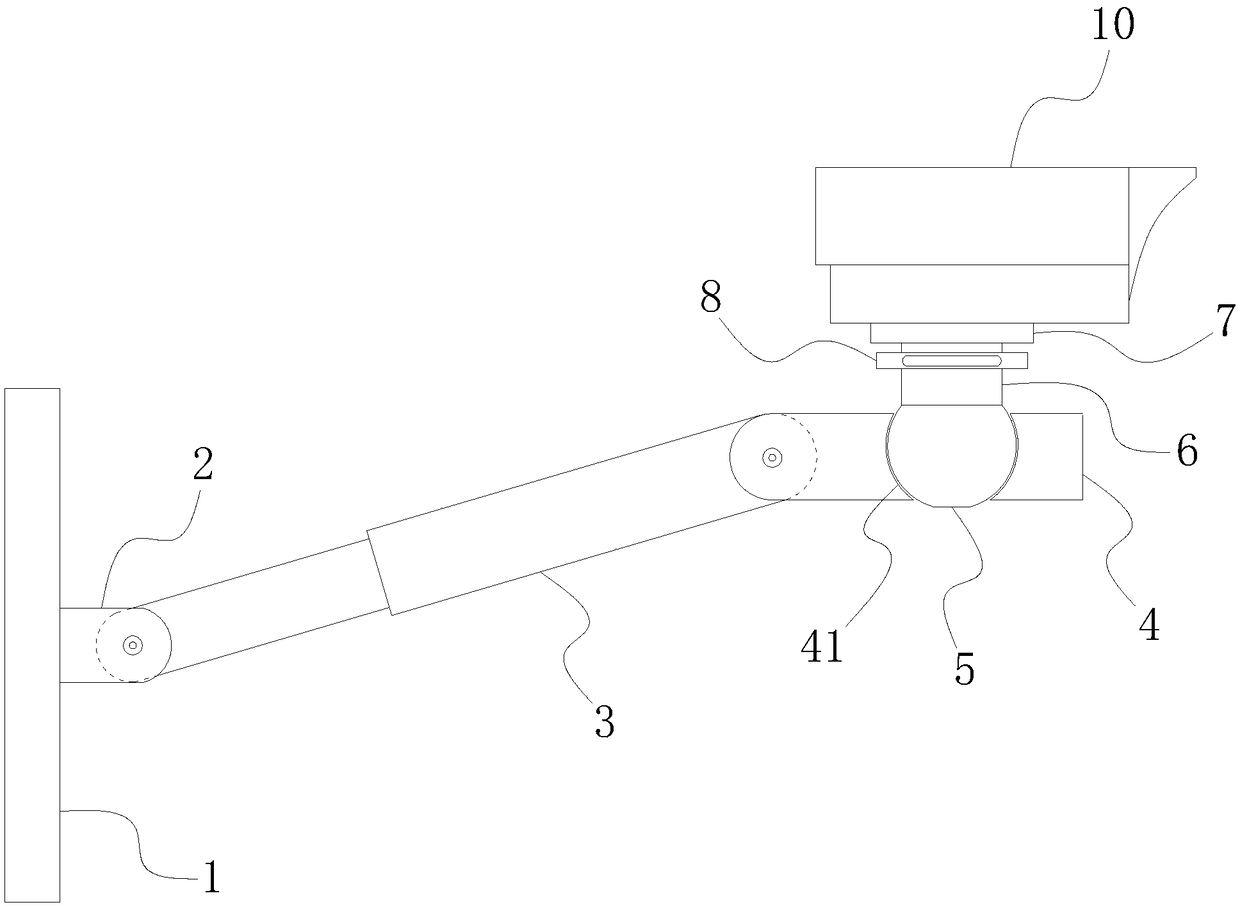
[0022] like Figure 1-Figure 4 As shown, a camera mounting bracket provided by the present invention includes the following components:

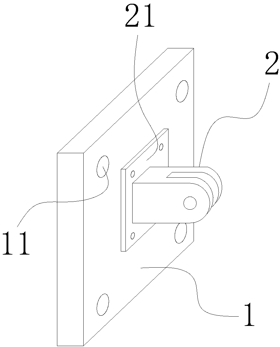
[0023] The fixed plate 1 is used for fixing to the wall, and the front of the fixed plate 1 is fixed with a connection ear seat 2;

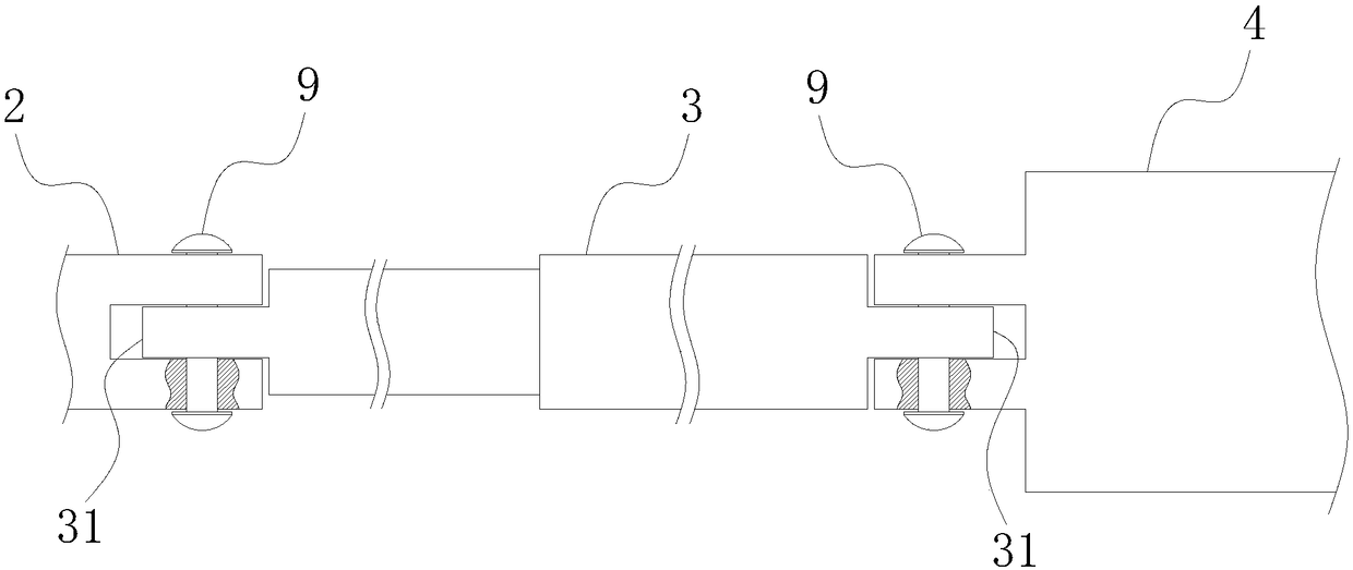
[0024] The telescopic rod 3 is rotatably connected to the connecting ear seat 2 at one end;

[0025] Support table 4, one end is rotatably connected with the end of the telescopic rod 3 away from the fixed plate 1; the inside of the support table 4 is provided with a mounting groove 41 whose wall surface is a spherical surface; preferably, as Figure 4 As shown, the support table 4 includes a front half 42 and a rear half 43, and the installation groove 41 is formed after the front half 42 and the rear half 42 are put together, ...


PUM


Abstract

The invention discloses a camera mounting rack which comprises a fixed plate, a telescopic rod, a support table, an angle adjusting ball and a mounting pipe, wherein the fixed plate is used for beingfixed to a wall surface; a connecting lug seat is fixed on the obverse side of the fixed plate; one end of the telescopic rod is rotatably connected with the connecting lug seat; one end of the support table is rotatably connected with the end, far away from the fixed plate, of the telescopic rod; a mounting groove is formed in the support table, and the wall surface of the mounting groove is a spherical surface; the angle adjusting ball is mounted in the mounting groove of the support table and can freely rotate in the mounting groove; and one end of the mounting pipe is fixed on the upper surface of the angle adjusting ball, a plate is fixed at the other end of the mounting pipe, and the plate is used for mounting and fixing a camera. The camera mounting rack can provide support for multi-angle adjustment and rotation of the camera; and under the circumstance that the mounting condition is more special, the aligned direction of the camera is more special or the aligned direction of the camera needs to be adjusted from time to time, the camera can meet the requirements, so that the defects of the existing mounting rack can be overcome.

Description

technical field [0001] The invention relates to the field of cameras, in particular to a camera mounting frame. Background technique [0002] The camera is widely used in the field of real-time monitoring, and the camera usually needs to be installed on the wall with the help of a mounting bracket. However, the existing mounting frame is usually an integrated structure, and after the camera is installed, the angle, direction, or angle of adjustment is very limited. [0003] However, at certain times, for example, the installation conditions are special, the camera needs to be aimed in a special direction, or the direction in which the camera is aimed will be adjusted from time to time. In the face of these situations, because the current mounting frame cannot provide support for the multi-angle adjustment and rotation of the camera, it is difficult to meet the installation requirements, and the installers and the users of the camera are also distressed. Contents of the in...

Claims


Application Information

Patent Timeline
IPC IPC(8): F16M13/02F16M11/04F16M11/14F16M11/16F16M11/28
CPCF16M13/02F16M11/04F16M11/14F16M11/16F16M11/28
Inventor 秦秋梅陈兴琼詹佳
Owner 泸州兴晨宇科技有限公司
Why Eureka
Try Eureka