AI technical title is built by Patsnap AI team. It summarizes the technical point description of the patent document.
A technology of display panel and display method, which can be applied to static indicators, instruments, etc., and can solve the problem of color shift in partial transparent areas.
Active Publication Date: 2019-01-04
BOE TECH GRP CO LTD
View PDF11 Cites 20 Cited by
Summary
Abstract
Description
Claims
Application Information
AI Technical Summary
This helps you quickly interpret patents by identifying the three key elements:
Problems solved by technology
Method used
Benefits of technology
Problems solved by technology
In response to this problem, someone proposed an under-screen camera solution. The camera is moved to the bottom of the screen by reducing the local pixel density and increasing the screen light transmittance. However, due to the decrease in pixel density and the influence of the sub-pixel rendering SPR algorithm, local transparent areas will appear. Color cast
Method used
Image
Click on the blue label to locate the original text in one second.
Reading with bidirectional positioning of images and text.
Examples
Embodiment 1
[0045] Such as Figure 5 As shown, this embodiment provides a display method for a display panel, the method specifically includes:
[0046] S1. Generate an original image composed of a matrix of virtual pixels 2 according to the image information.
[0047] Specifically, the original image generation unit in the display panel can be used to process the image information (that is, the content of a frame of image to be displayed) from the graphics card, and use it to generate an original image, which is composed of multiple A matrix of "points (that is, virtual pixels 2)", each virtual pixel 2 includes the original components of the three colors of red, green, and blue to represent the "amount" of the three colors of red, green, and blue at the "point" How much respectively.
[0048] Among them, the "component" in the above "original component" and the subsequent "display component" all refer to the "amount" of the color that should be displayed at the corresponding position, ...
Embodiment 2
[0067] Such as Figure 6 As shown, this embodiment provides a display panel, which can be displayed by using the display method in Embodiment 1. Wherein, the arrangement of pixels on the display panel may be consistent with that described in Embodiment 1; in particular, the display panel further includes: an original image generation unit, an original component acquisition unit, and a calculation unit.
[0068] Wherein, the original image generating unit is configured to generate an original image corresponding to the virtual pixel 2 according to the image information to be displayed.
[0069] Specifically, the original image generation unit is used to process image information (that is, the content of the image to be displayed) from the graphics card, etc., and use it to generate an original image. ", each virtual pixel 2 includes the original components of the three colors of red, green, and blue to represent the "amounts" of the three colors of red, green, and blue at the ...
PUM
Abstract
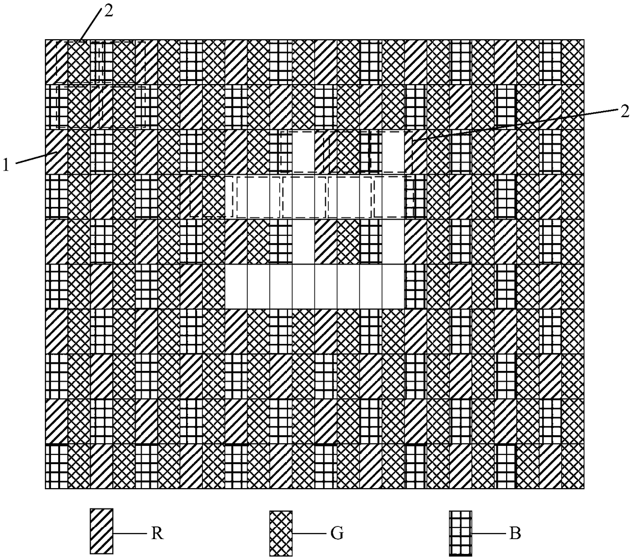
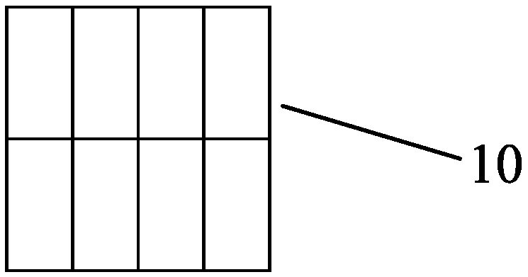
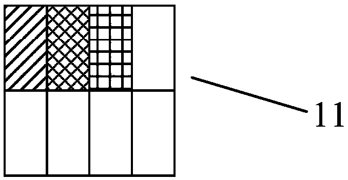
The invention provides a display panel and a display method, belonging to the technical field of display. The display panel includes: a repetition unit for setting sub-pixels of different colors; anda display unit for setting sub-pixels of different colors, wherein common sub-pixels are included in sub-pixels of different colors. The repetition unit includes a first repetition unit and a second repetition unit having the same sub-pixel area arrangement; at least a portion of the sub-pixel area in the first repeating unit is a vacant sub-pixel area; no sub-pixels are provided in the vacant sub-pixel area; each sub-pixel area of the second repeating unit is provided with a sub-pixel. The method comprises the following steps of: generating an original image corresponding to a virtual pixel according to image information to be displayed; controlling the original component of each color in the virtual pixel corresponding to the vacant sub-pixel area to be 0, and obtaining the original component of each color in the remaining virtual pixels. A display component of the sub-pixel is calculated based on a corresponding color original component in each virtual pixel corresponding to the sub-pixel.
Description
technical field [0001] The invention belongs to the field of display technology, and in particular relates to a display panel and a display method. Background technique [0002] With the development of display electronic products such as mobile phones, the increase in screen-to-body ratio has become a product trend. For example, front-facing cameras and other essential functional components of mobile phones must become a major factor restricting the increase in screen-to-body ratio. In response to this problem, someone proposed an under-screen camera solution. The camera is moved to the bottom of the screen by reducing the local pixel density and increasing the screen light transmittance. However, due to the decrease in pixel density and the influence of the sub-pixel rendering SPR algorithm, local transparent areas will appear. Color cast phenomenon. Contents of the invention [0003] The present invention aims at solving at least one of the technical problems in the pri...
Claims
Application Information
Patent Timeline
Application Date:The date an application was filed.
Publication Date:The date a patent or application was officially published.
First Publication Date:The earliest publication date of a patent with the same application number.
Issue Date:Publication date of the patent grant document.
PCT Entry Date:The Entry date of PCT National Phase.
Estimated Expiry Date:The statutory expiry date of a patent right according to the Patent Law, and it is the longest term of protection that the patent right can achieve without the termination of the patent right due to other reasons(Term extension factor has been taken into account ).
Invalid Date:Actual expiry date is based on effective date or publication date of legal transaction data of invalid patent.

