Combined fixator for femoral and tibial fixator

A technology of fixator and femur, applied in the direction of fixator, external fixator, medical science, etc.

Active Publication Date: 2019-01-11
YICHANG NO 2 PEOPLES HOSPITAL
View PDF4 Cites 3 Cited by
  • Summary
  • Abstract
  • Description
  • Claims
  • Application Information

AI Technical Summary

Problems solved by technology

Since the traction needle (N-2) is a slender polished rod, after the traction needle (N-2) is fastened and fixed, the traction needle (N-2) exists under the action of an external force and is very easy to move along the V (or reverse) direction. Risk of axial displacement towards rotation or in F (or reverse) direction

Method used


Image

  • Combined fixator for femoral and tibial fixator
  • Combined fixator for femoral and tibial fixator
  • Combined fixator for femoral and tibial fixator

Examples


Embodiment 1

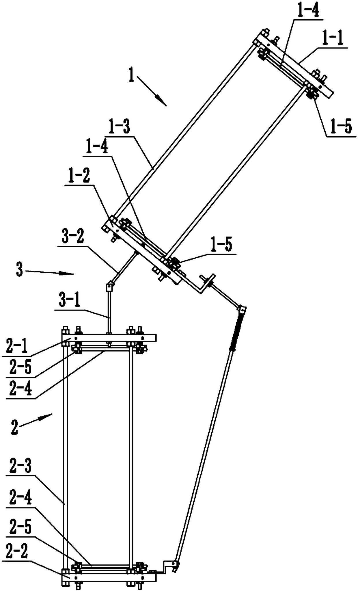
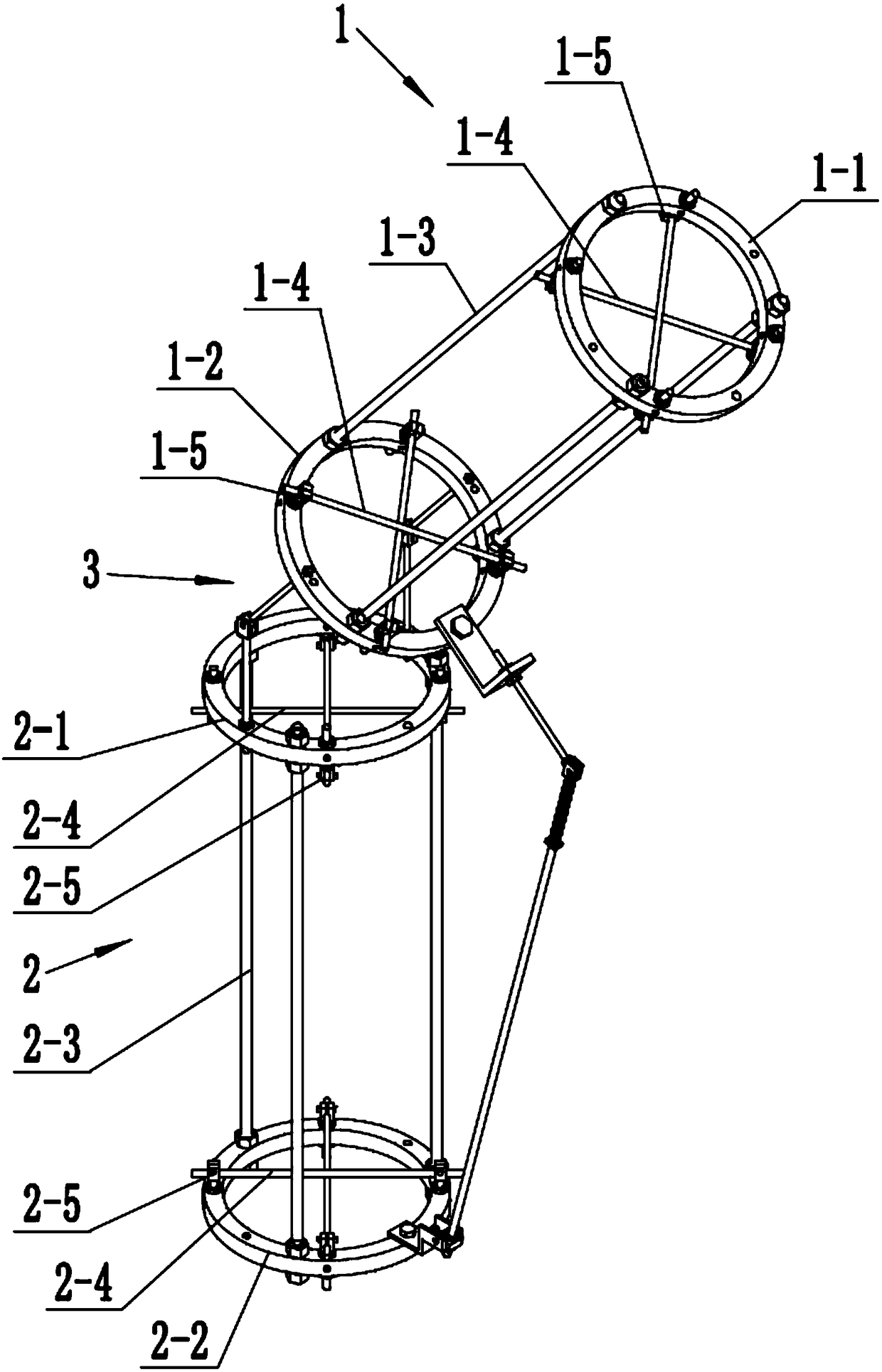
[0037] Embodiment one: see Figure 2-9 : A combination fixer for femur and tibia, comprising a femoral fixation bracket (1) and a tibial fixation bracket (2);

[0038] The femoral fixation bracket 1 includes an upper femoral collar 1-1, a lower femoral collar 1-2 and a first connecting rod 1-3, and the two ends of the first connecting rod 1-3 are connected with the femoral upper collar 1-1 respectively. It is fixedly connected with the lower femoral collar 1-2, and both the upper femoral collar 1-1 and the lower femoral collar 1-2 are provided with a femoral distraction pin fixer 1-5 for fixing the femoral distraction pin 1-4.

[0039] Preferably, both ends of the first connecting rod 1-3 are respectively adjustable and fixed to the upper femoral ring 1-1 and the lower femoral ring 1-2, so that the upper femoral ring 1-1 and the lower femoral ring 1 The -2 spacing can be adjusted to suit the fixation of different bone types. In this embodiment, there are three first connecti...

Embodiment 2

[0053] Embodiment 2: This embodiment is basically the same as Embodiment 1, the difference is:

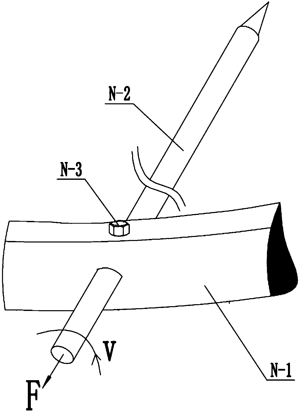
[0054] see Figure 10-11 , a bone nail fixer 4 is fixedly installed on the femoral fixation bracket 1 or / and the tibia fixation bracket 2 . This is not limited to the traction pin fixation at the two ends of the femur or tibia, but also can cooperate with the bone nail fixer 4 to place bone nails at different positions of the femur or tibia, so that the fractured position of the femur or tibia can be better reset.

[0055] In this example, see Figure 11, the bone nail fixer 4 includes a support beam 4-1, two arc rings 4-2 and several bone screw fixation devices 4-3; the support beam 4-1 is provided with a plurality of first A mounting hole 4-11, the two arc-shaped rings 4-2 are arranged at intervals and respectively fixed on the two first mounting holes 4-11, and the arc-shaped rings 4-2 are arranged in an arc-shaped distribution A plurality of second mounting holes 4-21, the b...


PUM


Abstract

A combined fixator for femoral and tibial comprises a femoral fixation bracket, a tibial fixation bracket and an articulation mechanism, wherein the femoral traction pin fixator comprises a femoral traction pin clip seat, a first bolt and a first positioning insertion plate, wherein a first deformation groove is arranged on the inner wall of the femoral traction pin clip hole of the femoral traction pin clip seat; A first positioning groove is arranged on the outer wall of the femoral traction needle, the first positioning plug plate is positioned in the first deformation groove and cooperatively inserted with the first positioning groove, or/and the tibial traction pin holder includes a tibial traction pin holder, a second bolt and a second positioning insert plate, wherein a second deformation groove is arranged on the inner wall of the tibial traction pin clip hole of the tibial traction pin clip base, a second positioning groove is arranged on the outer wall of the tibial tractionpin, and the second positioning insert plate is positioned in the second deformation groove and cooperatively inserted with the second positioning groove. The combined fixator for femoral and tibial can solve the problems of axial displacement or rotational loosening of the femoral traction needle and the tibial traction needle in the prior art.

Description

technical field [0001] The invention belongs to the technical field of orthopedic fixers, in particular to a combined fixer for femur and tibia. Background technique [0002] Joint fracture is the most common bone injury in daily life, especially with the development of transportation and construction industry, it shows an increasing trend. Therefore, the femur and tibia of the knee joint have displaced fractures, and surgical reduction and fixation are necessary. How to fix extremity fractures more easily and more firmly, and how to minimize the impact on the blood supply of the fracture so as to promote fracture healing have always been the focus and difficulty of orthopedic surgeons. [0003] A knee joint flexion contracture orthosis is currently disclosed, the femoral fixation bracket and the tibia fixation bracket are respectively sleeved on the femur and the tibia. During use, the femur and the tibia are respectively pierced with femoral traction pins and tibial tract...

Claims


Application Information

Patent Timeline
Patent Type & Authority Applications(China)
IPC IPC(8): A61B17/62A61B17/64
CPCA61B17/62A61B17/645A61B2017/564
Inventor 黄金友杨良枫张继平刘晓菊李作宏邱高高黄进成曾晶山
Owner YICHANG NO 2 PEOPLES HOSPITAL
Why Eureka
Try Eureka