A vacuum sealing device and vacuum tire mold

A vacuum sealing and tire mold technology, applied in tires, household appliances, other household appliances, etc., can solve the problems of enlarged gap, reduced sealing effect of base and middle mold sleeve, and low service life of sealing ring.

Active Publication Date: 2020-07-07
HIMILE MECHANICAL SCI & TECH (SHANDONG) CO LTD
View PDF7 Cites 0 Cited by
  • Summary
  • Abstract
  • Description
  • Claims
  • Application Information

AI Technical Summary

Problems solved by technology

However, during the use of the mold, due to the reduction of matching precision, the gap between the middle mold sleeve and the protrusion of the base will become larger, and the sealing effect of the base and the middle mold sleeve will be reduced, resulting in that the vacuum degree inside the mold cannot meet the use requirements.
[0004] In addition, the frequent opening and closing of the mold will cause the wear of the sealing ring, resulting in a low service life of the sealing ring

Method used


Image

  • A vacuum sealing device and vacuum tire mold
  • A vacuum sealing device and vacuum tire mold
  • A vacuum sealing device and vacuum tire mold

Examples


Embodiment 1

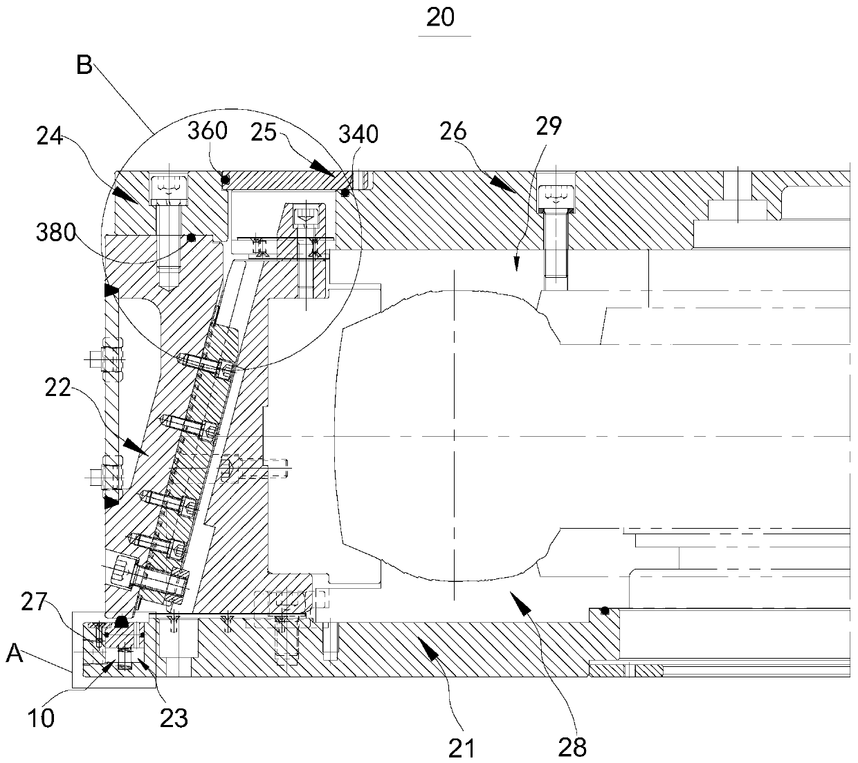
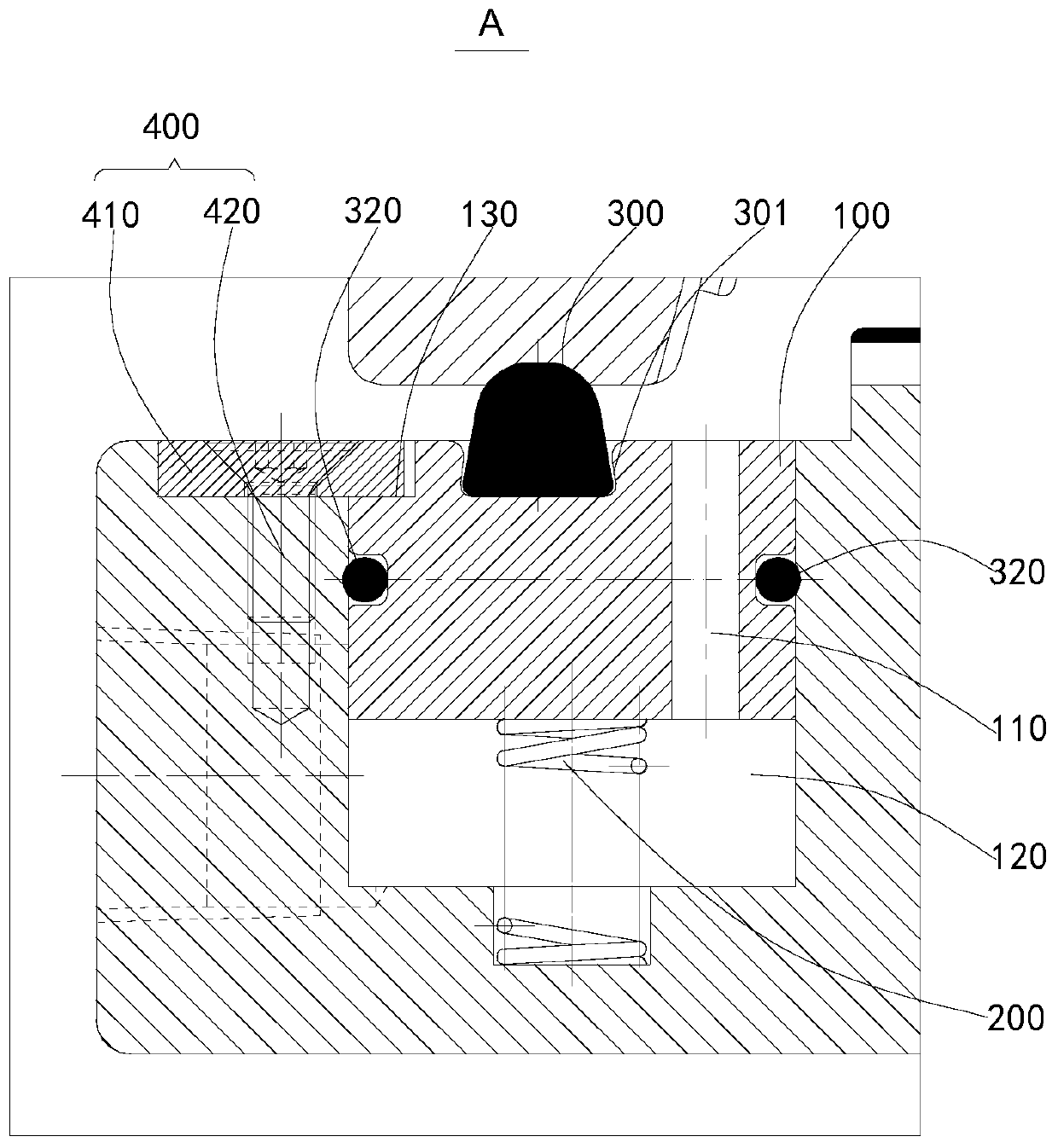
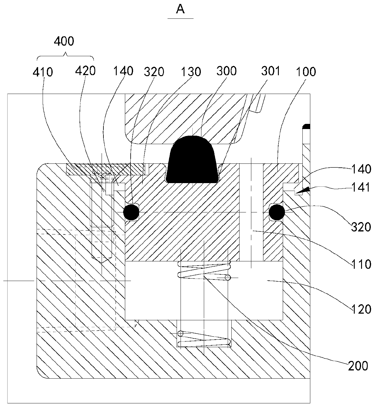
[0063] Please refer to figure 1 and figure 2 , as can be seen from the figure, a vacuum sealing device 10 includes an adjustment part 100, an elastic device 200 and a first sealing member 300, which cooperate with the base 21 and the middle mold case 22 of the vacuum tire mold 20 to seal the vacuum. tire mold 20.

[0064] Further, the base 21 has an annular groove 23 arranged in the circumferential direction, and the adjusting part 100 is arranged in the annular groove 23 through the elastic device 200; the elastic device 200 is configured to provide an elastic force that makes the adjusting part 100 close to the middle die casing 22; the first The sealing member 300 is embedded in the end of the adjustment part 100 close to the middle mold casing 22. The first sealing member 300 is configured to realize the sealing between the middle mold casing 22 and the adjustment part 100; the vacuum sealing device 10 also includes a second sealing member 320 ; The second seal 320 is d...

Embodiment 2

[0099] Figure 5 Schematic diagram of the structure of the vacuum sealing device provided in Embodiment 2 of the present invention; Figure 6 for Figure 5 Partial schematic diagram at C.

[0100] Please refer to Figure 5 and Figure 6 , it can be seen from the figure that the vacuum sealing device in this embodiment is consistent with the embodiment, the difference is that along the radial direction of the tire mold, the fifth sealing member 380 is embedded in the mounting ring 24 and the middle mold Between sets of 22.

[0101] The mounting ring 24 is provided with a protruding ring that matches the middle mold cover 22, and the protruding ring is pressed against the corresponding matching portion of the middle mold cover 22, and a fifth seal 380 is provided at the contact fit, and the middle mold cover 22 and the mounting ring 24 There is no need for seals on the contact surfaces in the radial direction of the mold. When it is necessary to adjust the mold preload, a ...

Embodiment 3

[0104] Figure 7 Schematic diagram of the structure of the vacuum sealing device provided in Embodiment 3 of the present invention; Figure 8 for Figure 7 Partial schematic diagram at D in middle.

[0105] Please refer to Figure 7 and Figure 8 , it can be seen from the way, and it can be seen from the figure that the vacuum sealing device in this embodiment is roughly the same as in Embodiment 1, the difference is that one end of the upper sealing ring 25 is set on the upper cover 26, and the other end is set On the radial inner side of the middle mold casing 22, the mounting ring 24 is not in contact with the sealed inner cavity, and a third sealing member 340 is provided between the upper cover 26 and the upper sealing ring 25, and the upper sealing ring 25 and the middle mold casing 22 A fifth seal 380 is provided therebetween.

[0106] The upper sealing ring 25 and the middle die sleeve 22 isolate and seal the inner cavity of the mounting ring 24 , and no seal is a...


PUM


Abstract

The present invention provides a vacuum sealing device and a vacuum tire mould. The vacuum sealing device includes an adjusting part, an elastic device and a first sealing element. A base has a circular slot disposed in the circumferential direction. The adjusting part is disposed in the circular slot through the elastic device. The elastic device is configured to provide an elastic force to enable the adjusting part to approach a middle mould sleeve. The first sealing element is embedded in the end of the adjusting part close to the middle mould sleeve. The first sealing element is configuredto realize sealing between the middle mould sleeve and the base. The vacuum sealing device further includes a second sealing element disposed between the adjusting part and the side wall of the circular slot. Such a vacuum sealing device improves insufficient vacuum degree in the prior art during mould closing and excessive wear to the seal ring.

Description

technical field [0001] The invention relates to the technical field of tire molds, in particular to a vacuum sealing device and a vacuumized tire mold. Background technique [0002] At present, radial tires are more and more widely used, especially tires with complex tread patterns. The more complex the tread pattern, the easier it is for the mold to have poor exhaust during the tire building process, resulting in lack of rubber in the tire and affecting the appearance of the tire. In order to discharge the gas smoothly, the traditional active mold processes a large number of vent holes on the cavity surface, and the gas between the tire blank and the mold tread is passively discharged through the vent holes. When the tire pattern structure is complex and the pattern depth is large , Affected by the temperature and the fluidity of the green tire after heating, it is very easy to appear air pockets, resulting in lack of rubber in the tire and unclear edges of the tire, which ...

Claims


Application Information

Patent Timeline
Patent Type & Authority Patents(China)
IPC IPC(8): B29C33/00B29C33/10B29L30/00
CPCB29C33/0038B29C33/10B29L2030/00
Inventor 周金丛杜永强王通王家栋翟宝堂杜平刘卫华单既强张伟
Owner HIMILE MECHANICAL SCI & TECH (SHANDONG) CO LTD
Why Eureka
Try Eureka