Three-lock clamp locking mechanism with redundancy design

A technology of locking mechanism and buckle, which is applied in the direction of friction-clamped detachable fasteners, connecting components, mechanical equipment, etc., to achieve the effects of preventing axial deflection, easy operation, and reliable fixing method

Active Publication Date: 2019-01-11
CHINA AVIATION OPTICAL-ELECTRICAL TECH CO LTD
View PDF6 Cites 2 Cited by
  • Summary
  • Abstract
  • Description
  • Claims
  • Application Information

AI Technical Summary

Problems solved by technology

[0003] The purpose of the present invention is to design a locking structure with three buckles and satisfy redundant protection at the same time, so as to solve the technical problem of simultaneously satisfying the locking structure and redundant protection

Method used


Image

  • Three-lock clamp locking mechanism with redundancy design
  • Three-lock clamp locking mechanism with redundancy design
  • Three-lock clamp locking mechanism with redundancy design

Examples


Embodiment Construction

[0018] Below in conjunction with accompanying drawing and embodiment the present invention will be further described:

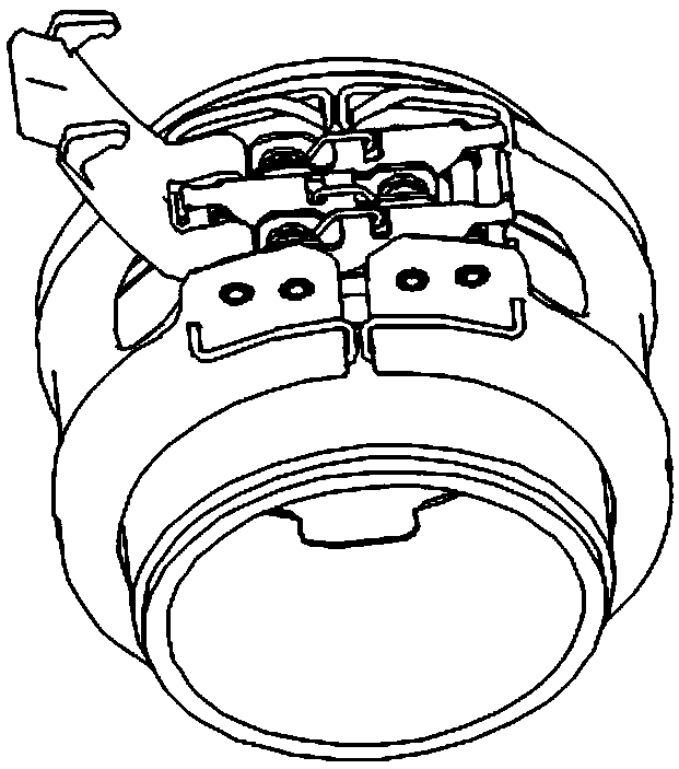
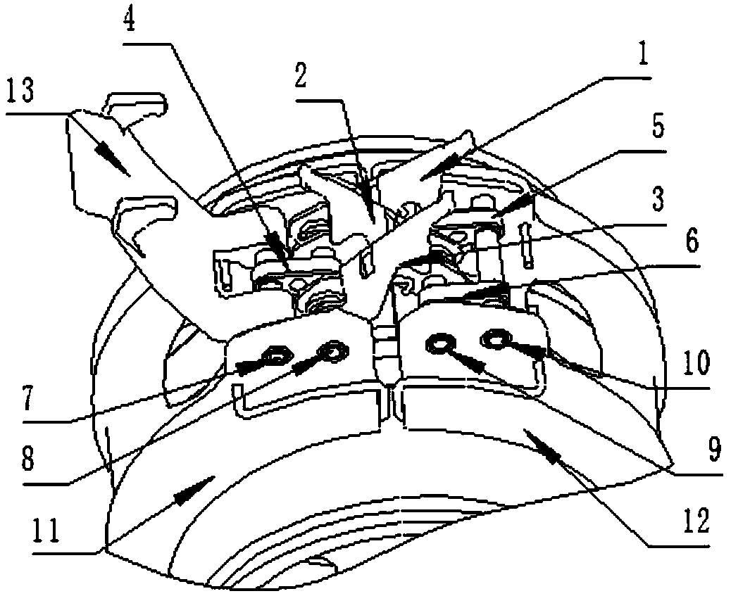
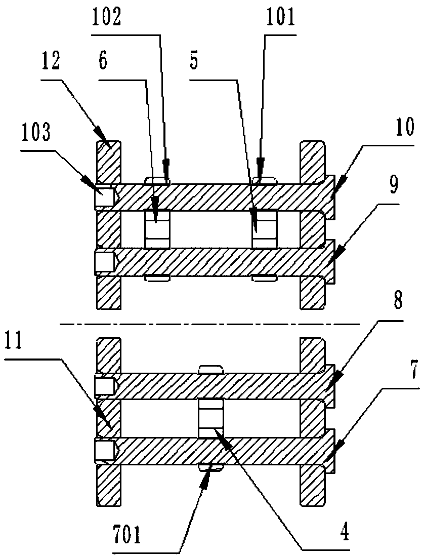
[0019] The three-dimensional schematic diagram of the three-lock clamp locking mechanism with redundant design of the present invention is as follows figure 1 As shown, the following combination figure 2 , image 3 , Figure 4 The specific embodiment will be described in detail.

[0020] The three-lock clip clamp locking mechanism with redundant design of the present invention, the overall structure is as follows figure 2 As shown, the clamp locking mechanism includes A lock 1, B lock 2, C lock 3, A connecting piece 4, B connecting piece 5, C connecting piece 6, A pin 7, B pin 8. C pin shaft 9, D pin shaft 10, first clamp housing 11 and second clamp housing 12; the relative positions of the A lock 1, B lock 2, and C lock 3 are triangular Distribution: A lock 1 is connected to B pin 8, B lock 2 is connected to C pin 9, C lock 3 is connected to B pin 8; ...


PUM


Abstract

The invention belongs to the technical field of quick locking, and relates to a three-lock clamp locking mechanism with a redundancy design. The locking mechanism is composed of four hinge pins, threelock clamps, a pair of auxiliary lock clamps and three connecting pieces. The relative positioned of the three connecting pieces connecting the hinge pins are distributed in a triangular mode, and are coplanar with center faces of the three lock clamps at the corresponding positions. The locked lock clamps can cover the connecting pieces at the corresponding positions. Square grooves are formed in the centers of the root positions of the auxiliary lock clamps. The three lock clamps are adopted to achieve locking of the locking mechanism. A redundancy protection structure is arranged, and reliability of the locking structure is better improved.

Description

technical field [0001] The invention belongs to the technical field of fast locking, and relates to a three-lock clamp locking mechanism with redundant design. Background technique [0002] The clamp-type locking structure is widely used in engineering applications. The principle of the common locking structure is the same. The locking forms include double-lock structure, three-lock structure and four-lock structure. On the premise of convenient operation, the greater the number of locks, the higher the reliability. For aviation products used in important parts, there is a requirement for redundant design. When one part fails, other parts can work normally without affecting product performance, which minimizes the risk of product failure. Therefore, for the clamp locking structure, the lock locking method alone cannot fully meet the requirements. Generally, the connection components with redundant design use the combination of locks and auxiliary locks for redundant locki...

Claims


Application Information

Patent Timeline
Patent Type & Authority Applications(China)
IPC IPC(8): F16B2/20
CPCF16B2/20
Inventor 李斌刘帅张磊卢明胜
Owner CHINA AVIATION OPTICAL-ELECTRICAL TECH CO LTD
Why Eureka
Try Eureka