Pay-off retainer and use method thereof

A technology of retainer and pay-off reel, applied in the field of electric power, can solve the problems of too fast speed, too loose winding of the reel, affecting use, etc., and achieve the effect of maintaining balance

Active Publication Date: 2019-01-18
WEIHAI POWER SUPPLY COMPANY OF STATE GRID SHANDONG ELECTRIC POWER COMPANY +1
View PDF12 Cites 0 Cited by
  • Summary
  • Abstract
  • Description
  • Claims
  • Application Information

AI Technical Summary

Problems solved by technology

When wiring, the staff all pull the wires with bare hands. When pulling the wires with bare hands, the staff cannot accurately control the pulling force. Often the pulling force is too strong and the speed is too fast. Under the action of inertia, the wires will continue to go out. At this time, if the staff cannot immediately route the pulled out wires, a large number of pulled out wires will gather locally and serious line knotting will occur; when the wires are taken up, the staff still It...

Method used


Image

  • Pay-off retainer and use method thereof
  • Pay-off retainer and use method thereof
  • Pay-off retainer and use method thereof

Examples


Embodiment 1

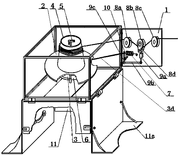
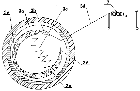
[0034] Such as figure 1 As shown, a pay-off holder includes an operating box, a pay-off part, and a tension control part. One side of the operating box is provided with an openable and closeable operating door 1, and the pay-off part is arranged in the operating box. The pay-off part includes pay-off reel 2 and brake mechanism 3. The top of the pay-off reel is provided with a spool 4, the bottom of the pay-off reel 2 is fixed on the bottom surface of the operating box by a rotating shaft 6, and the upper end of the rotating shaft is connected with the rotating handle 5 is connected, the rotating handle 5 is arranged in the wire support 4, the rotating handle in this embodiment is a folding rotating handle with a folding joint, the braking mechanism 3 is arranged on the shaft, the braking mechanism 3 includes a brake drum 3a, a brake pad 3b, a return spring 3c and a brake rib 3d. The brake drum 3a is installed on the inner wall of the shaft 6 to rotate with the shaft. Two brake p...

Embodiment 2

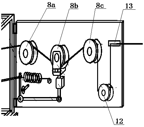
[0042] The difference between this embodiment 2 and embodiment 1 lies in: on the basis of embodiment 1, a wire take-up pulley 12 and a wire clamp 13 are added, and the wire take-up pulley 12 is fixed on the operating door and is located on the second bearing On the lower side of the force pulley 8c, the second force-bearing pulley 8c and the wire take-up pulley 12 are matched up and down; the wire clamp 13 is fixed at the outer end of the operating door, and the position of the wire clamp 13 and the wire take-up pulley 12 is up and down In cooperation, a semi-open C-shaped wire clamping groove is provided on the wire clamping device 13, and the opening degree of the wire clamping groove is adjustable; the sensing pulley 8b is connected to the pulley frame via the axle, and one end of the axle is blocked by the sliding block, The other end of the axle is blocked by an adjusting plug.

[0043] The use method of this embodiment 2 includes the following steps:

[0044] 1) Preparation ...


PUM


Abstract

The invention relates to a pay-off retainer. The pay-off retainer comprises an operation box, a pay-off part and a tension control part, wherein the pay-off part comprises a pay-off spool and a braking mechanism, the top of the pay-off spool is provided with a wire supporting cylinder, the bottom of the pay-off spool is connected with a rotating shaft, the braking mechanism is arranged on the rotating shaft, the braking mechanism comprises a brake drum, a brake block, a return spring and a brake rib, the tension control part is arranged on an operation door, the tension control part comprisesa control spring, a pay-off pulley block, a connecting rod mechanism and a limiting handle, one end of the control spring is fixedly connected with the operation door, the other end of the control spring is connected with the brake rib of the braking mechanism, the pay-off pulley block comprises a first force bearing pulley, a second force bearing pulley and a sensing pulley, the first force bearing pulley and the second force bearing pulley are fixed at the inner end and outer end of the inner side face of the operation door respectively, and the sensing pulley is slidably arranged in a vertical sliding groove in the inner side face of the operation door through a sliding block; the connecting rod mechanism comprises a sensing rod, a linkage rod and a control rod, and a control handle isrotatably connected to the operation door through a mounting end.

Description

Technical field [0001] The present invention relates to the field of electric power technology, in particular to a pay-off holder that is convenient to carry, safe to use, and fully mechanically operated. Background technique [0002] The construction chief of the overhead line needs to use some tools and equipment to take certain methods to complete the assembly and maintenance of each component to ensure the safe operation of the line. Workers generally simply pull out the wires from the reel when wiring and taking up wires in the field. When wiring, the staff are all hand-drawn wires, and the staff cannot accurately control the pulling force when they are pulling the wires. The pulling force is often too strong and the speed is too fast. When the pulling force is too large, the wire exiting speed is too fast, and Under the action of inertia, the wires will continue to go out. At this time, if the staff are unable to wire the pulled wires immediately, a large number of pulled ...

Claims


Application Information

Patent Timeline
IPC IPC(8): B65H75/38B65H75/44
CPCB65H75/38B65H75/4439B65H2701/34
Inventor 任增田王赜洋孙维杰孙涛孙荣光林向东李伟王庆宋昆刘明义孔德怀段海军徐杰
Owner WEIHAI POWER SUPPLY COMPANY OF STATE GRID SHANDONG ELECTRIC POWER COMPANY
Why Eureka
Try Eureka