Rotating assembly and support

A technology for rotating components and connectors, applied in the direction of machine/support, connecting member, supporting machine, etc., can solve problems such as cable exposure, cable damage, and excessive twisting of cables

Inactive Publication Date: 2019-01-18
ZHEJIANG DAHUA TECH CO LTD
View PDF5 Cites 0 Cited by
  • Summary
  • Abstract
  • Description
  • Claims
  • Application Information

AI Technical Summary

Problems solved by technology

[0004] For example, (1) Some brackets can only be adjusted in two directions of rotation, so there is a large dead angle of rotation, and at the same time, some brackets do not have a structural design for internal wiring, resulting in exposed cables;
[0005] (2) Some brackets do not have a limit structure. When adjusting the rotation angle of the bracket, it is easy to separate the bracket (components connected in rotation) and at the same time, it is easy to cause excessive twisting of the cable, causing damage to the cable

Method used


Image

  • Rotating assembly and support
  • Rotating assembly and support
  • Rotating assembly and support

Examples


Embodiment Construction

[0051] In order to enable those skilled in the art to better understand the technical solutions of the present invention, the embodiments of the present invention will be described in detail below in conjunction with the accompanying drawings.

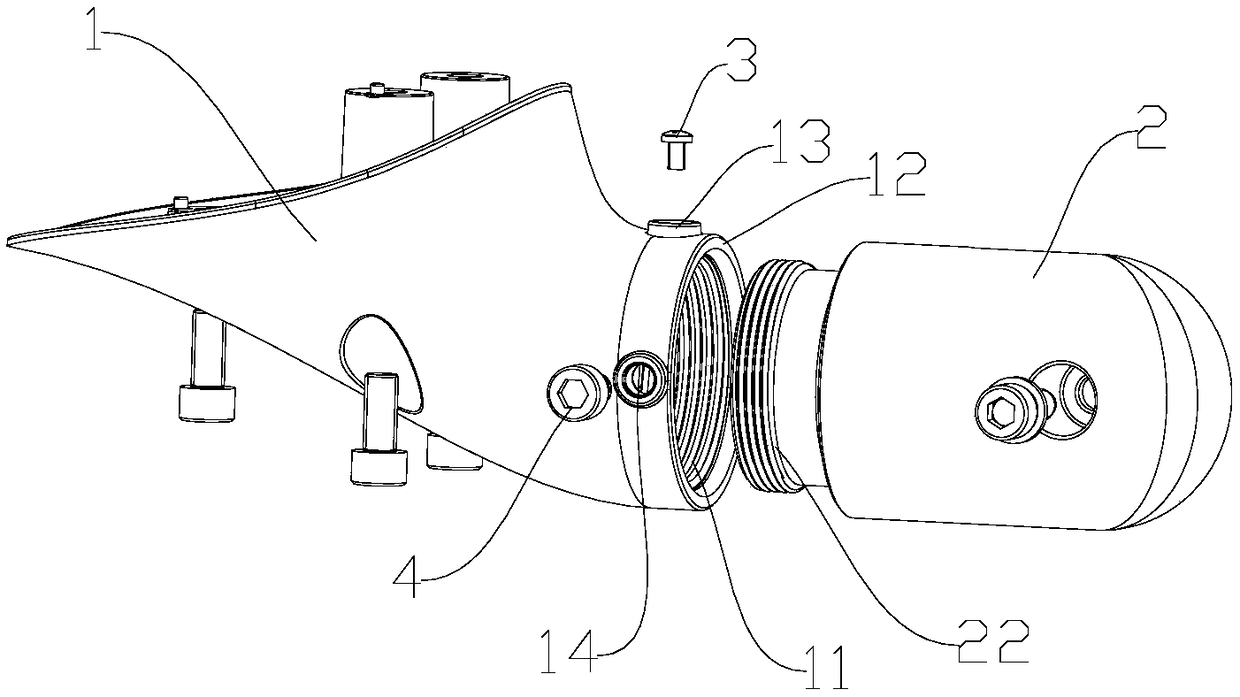
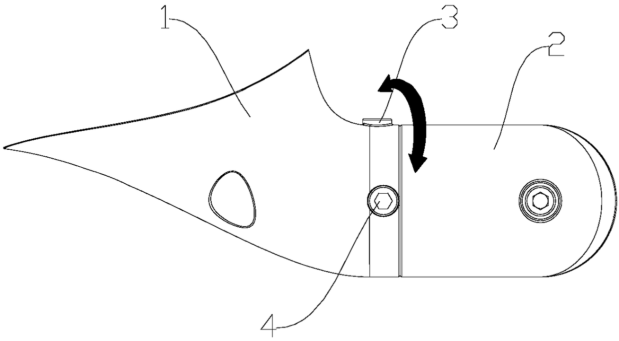
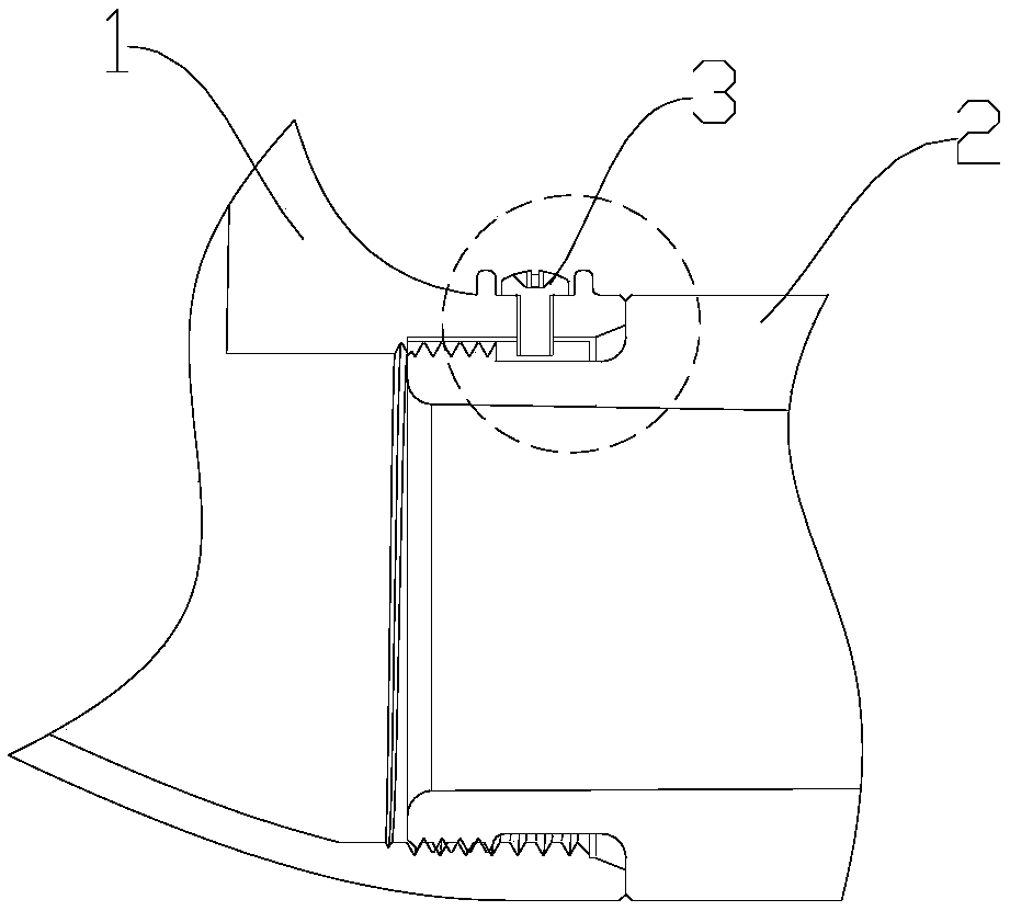
[0052] On the one hand, the embodiment of the present invention provides a rotating assembly, the rotating assembly includes a first connecting piece, a second connecting piece and a limiting structure;

[0053] Wherein, the end surface of the first end of the first connecting piece has a connecting hole, and the inner wall of the connecting hole has an internal thread; the outer circumference of the first end of the second connecting piece has an external thread for cooperating with the connecting hole; the limiting structure It is arranged on the first connecting piece and the second connecting piece, and is used for limiting the maximum rotation angle between the first connecting piece and the second connecting piece to 360° when the...


PUM


Abstract

The embodiment of the invention provides a rotating assembly and a support, and relates to the technical field of video monitoring. The technical problem that in the prior art, a rotating assembly hasno rotating angle limiting function or disengaging function is solved. The rotating assembly comprises a first connecting piece, a second connecting piece and a limiting structure, wherein a connecting hole is formed in the end face of the first end, and an internal thread is arranged at the inner wall of the connecting hole; the periphery of the first end is provided with an external thread forbeing in cooperative screw connection with the connecting hole; the limiting structure is arranged on the first connecting piece and the second connecting piece and used for limiting the maximum rotating angle between the first connecting piece and the second connecting piece to be 360 degrees after the first connecting piece and the second connecting piece are in screw connection. The rotating assembly can achieve limiting of the rotating range (the maximum rotating angle) between the first connecting piece and the second connecting piece, and can ensure that the first connecting piece and the second connecting piece cannot be disengaged after being in screw connection.

Description

technical field [0001] The invention relates to the technical field of video monitoring, in particular to a rotating assembly and a bracket. Background technique [0002] Nowadays, the application of surveillance cameras is more and more extensive, and users have more requirements for the image acquisition range of cameras. ), the camera cable will not twist. [0003] Surveillance cameras in the prior art generally fix the camera at an installation location (such as a wall) through a rotatable bracket, but the brackets in the prior art still have many shortcomings. [0004] For example, (1) Some brackets can only be adjusted in two directions of rotation, so there is a large dead angle of rotation, and at the same time, some brackets do not have a structural design for internal wiring, resulting in exposed cables; [0005] (2) Some brackets do not have a limit structure. When adjusting the rotation angle of the bracket, it is easy to separate the bracket (components connec...

Claims


Application Information

Patent Timeline
IPC IPC(8): F16M13/02F16M11/12F16M11/08F16M11/10F16M11/18F16B7/18
CPCF16B7/18F16M11/08F16M11/10F16M11/121F16M11/18F16M13/02F16M2200/021
Inventor 刘占龙盛楠
Owner ZHEJIANG DAHUA TECH CO LTD
Why Eureka
Try Eureka