
Universal joint window cleaner

A technology of a window cleaner and a universal joint, applied in the field of cleaning supplies, can solve problems such as the inability to perform window cleaning work well, the inability to adjust the distance between the two magnets, and the inability to achieve the original intention of the design, so as to achieve better cleaning effects and improve User experience, labor-saving effect of magnetic adjustment process

Pending Publication Date: 2019-01-25
HEBEI JIESHIBAO DAILY PLASTIC PROD CO LTD
View PDF6 Cites 0 Cited by
  • Summary
  • Abstract
  • Description
  • Claims
  • Application Information

AI Technical Summary

Problems solved by technology

This kind of window cleaner can't realize the window cleaning work very well. Obviously, there is no way to adjust the use distance between the two magnets, and there is sliding friction with the window glass, and the running resistance is large. The scrubbing process is very laborious and cannot reach the product. original design

Method used


Image

  • Universal joint window cleaner
  • Universal joint window cleaner
  • Universal joint window cleaner

Examples


Embodiment 1

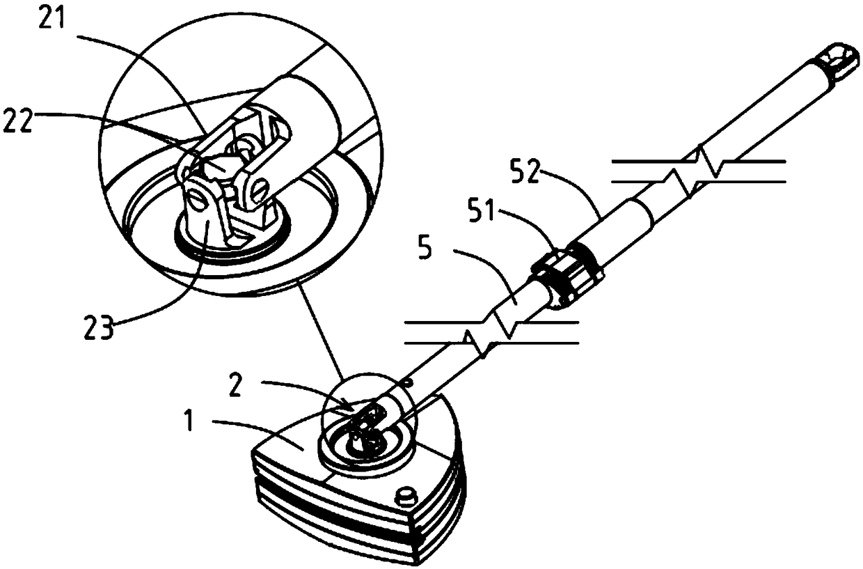
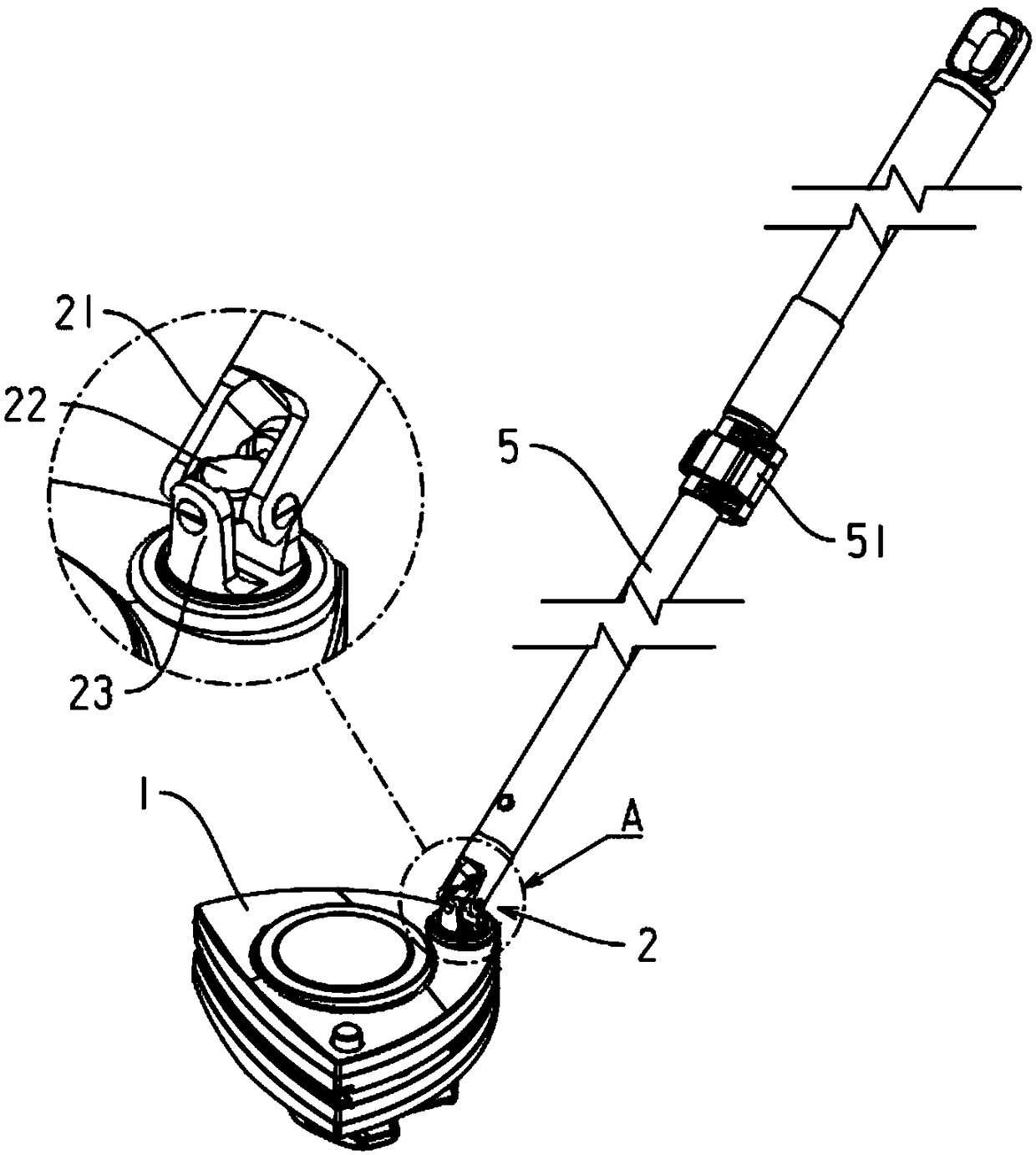
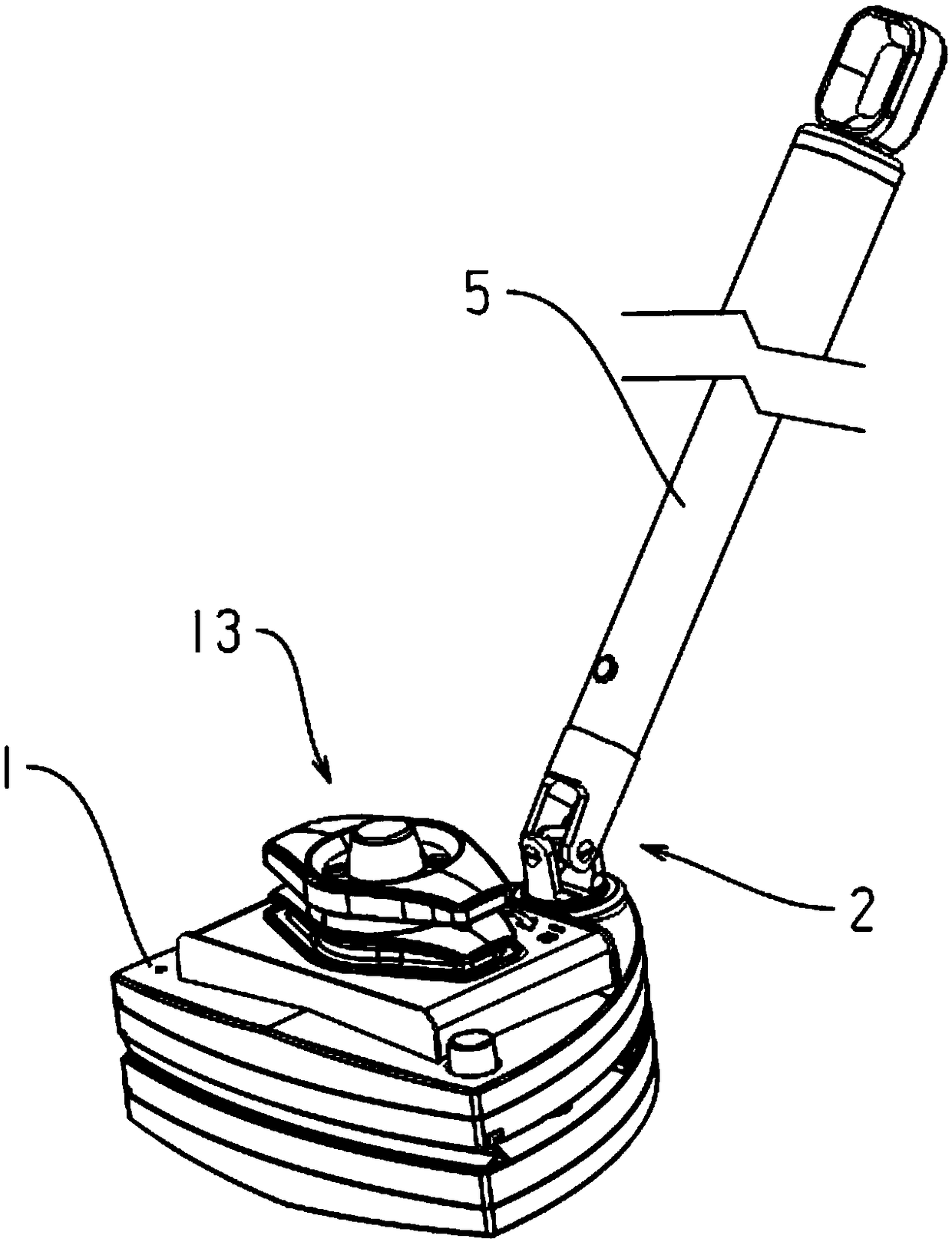
[0053] Embodiment 1: a kind of universal joint type window cleaner, as Figure 1.1 to Figure 2.1 as well as Figure 3 to Figure 9 As shown, it includes a wiper body 1 and a universal joint 2 that is movably connected to the wiper body, as Figure 1.1 and 2.1 As shown, the universal joint includes a first universal joint fork 21, a cross shaft 22 and a second universal joint fork 23, and the four ends of the cross shaft are four ends 221, as Figure 2.1 As shown, two of the opposite ends are rotatably connected with the first universal joint yoke, and the other two opposite ends are rotatably connected with the second universal joint yoke, while the second The universal joint fork is rotatably connected with the wiper body, and the wiper body can rotate in any direction through the universal joint.

[0054] The first universal joint yoke is one of the following two structures:

[0055] The first type is that the end of the first universal joint yoke away from the cross shaft...

Embodiment 2

[0084] Embodiment 2: a kind of universal joint type window cleaner, as Figure 10As shown, the structure is the same as that of Embodiment 1, except that the magnetic adjustment mechanism includes a magnetic assembly 131, a screw 132, and a magnetic adjustment knob 133 that drives the magnetic assembly away from or close to the second wiper. One end of the screw is connected with the magnetic adjustment knob, and the other end of the screw passes through the screw hole 116 of the first wiper and is connected with the magnetic assembly;

[0085] The surface of the first wiper in contact with the glass is provided with an inwardly recessed groove 113, the thickness of the magnetic component is smaller than the depth of the groove, and the magnetic component is located in the groove and exposed to the first Wipe the surface of the contact body with the glass, and rotate the magnetic adjustment knob to drive the screw up and down so as to push the magnetic assembly away from or cl...


PUM


Abstract

The invention discloses a universal joint window cleaner, comprises a wiper body and a universal joint movably connected to the wiper body, universal joints include the tenth universal joint fork, cross shaft and second universal joint fork, the four ends of the cross shaft are four ends, wherein two opposite ends are rotatably connected with the first universal joint fork, the other two oppositeends are rotatably connected with the second universal joint fork, or the two vertical ends of the cross shaft are two ends, wherein one end is rotatably connected with the first universal joint fork,and the other end is rotatably connected with the second universal joint fork; at the same time, the second universal joint is rotatably connected with the eraser body, and the erase body can rotatein any direction through the universal joint. As the universal joint is rotatably connected with the wiping body, the universal rotation of the wipe body can be realized, and the omni-directional scrubbing of the glass can be realized, in particular, the edge corner of the glass window can be cleaned; and the rotation process is flexible, labor-saving, simple and convenient to operate.

Description

technical field [0001] The invention belongs to the technical field of cleaning supplies, in particular to a window cleaner. Background technique [0002] Various types of glass windows are widely used in homes, office buildings, hotels, etc., but the glass is often polluted by dust, rain and other pollutants, it is easy to get dirty, and it needs to be cleaned from time to time. The cleaning of glass windows has become an increasingly important task. Big cleaning conundrum. Therefore, since the eighties in last century, there has been a window cleaner in my country, which is suitable for trains, automobiles, high-rise outer windows and has difficulties in wiping. Its structure is simple, easy to operate, and strong in practicability. [0003] The window cleaner mainly includes a handle and a wiper, the handle and the wiper are connected, and the wiper is driven by the handle to wipe the glass, but the rotation direction between the handle and the wiper in the existing wind...

Claims


Application Information

Patent Timeline
Patent Type & Authority Applications(China)
IPC IPC(8): A47L1/06A47L1/12
CPCA47L1/06A47L1/12
Inventor 任永旺
Owner HEBEI JIESHIBAO DAILY PLASTIC PROD CO LTD
Learn More