
A method for increasing that maximum output power of an IPM motor control of an electric vehicle
A technology of maximum output power and motor controller, which is applied in the direction of motor generator control, motor control, AC motor control, etc., can solve the problems of limited output power improvement and influence on motor operation performance, and achieve the effect of improving accuracy
- Summary
- Abstract
- Description
- Claims
- Application Information
AI Technical Summary
Problems solved by technology
Method used
Image

Examples
Embodiment Construction
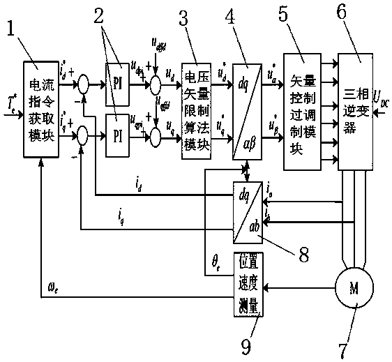
[0075] Example figure 1 As shown, the present invention is used to improve the method for the maximum output power of the electric vehicle IPM motor controller, and the motor controller is sequentially connected with a current command acquisition module 1, a proportional integral controller 2, a voltage vector limiting algorithm module 3, and a coordinate inverse conversion module 4. The vector control overmodulation module 5 and the three-phase inverter 6 drive the motor 7, the output signal of the three-phase inverter 6 is fed back to the proportional integral controller 2 through the coordinate conversion module 8, and the position and speed signals of the motor 7 are measured by the position and speed Module 9 feeds back to the current command acquisition module 1, coordinate inverse conversion module 4 and coordinate conversion 8 respectively, where the current command acquisition module 1 inputs the given torque of the motor in the full speed range This method comprises...
PUM
 Abstract
Description
Claims
Application Information