keyboard

A technology of keyboards and keycaps, which is applied in the direction of emergency actuators, contact operating mechanisms, electrical components, etc., and can solve the problems of large height space for keys, considerable thrust, and damage to the display screen.

Active Publication Date: 2019-12-03
DARFON ELECTRONICS (SUZHOU) CO LTD +1
View PDF5 Cites 0 Cited by
  • Summary
  • Abstract
  • Description
  • Claims
  • Application Information

AI Technical Summary

Problems solved by technology

However, due to the cross pivot design of the scissors support adopted by the above-mentioned scissors support device, the key needs a large height space, so when the upper cover and the lower case of the notebook computer are folded, in order to avoid being arranged on the lower case The keycap on the body hurts the display screen arranged on the upper cover, and there is often a gap between the upper cover and the lower shell to accommodate the keycap, which will limit the appearance and size design of the notebook computer, and is not conducive to the design of the notebook computer. Thin design
[0004] In order to solve the above problems, a lower base plate is usually arranged under the upper base plate of the keyboard. The lower base plate can slide horizontally relative to the upper base plate and a fixed structural member is formed at the position of the scissor foot support corresponding to each key. When the bottom plate is slid to the retracted position relative to the upper bottom plate, each fixed structural member will push the scissor foot support of the corresponding button to pivot downward, so that the keycap sinks to avoid the above-mentioned damage to the display screen. But because the number of keys on the keyboard is at least nearly a hundred, if only the above-mentioned single bottom plate is used to control the lifting of each keycap on the keyboard, a considerable thrust will be required

Method used


Image

  • keyboard
  • keyboard
  • keyboard

Examples


Embodiment Construction

[0053] The aforementioned and other technical contents, features and effects of the present invention will be clearly presented in the following detailed description of a preferred embodiment with reference to the drawings. The directional terms mentioned in the following embodiments, such as: up, down, left, right, front or back, etc., are only directions referring to the attached drawings. Accordingly, the directional terms are used to illustrate and not to limit the invention.

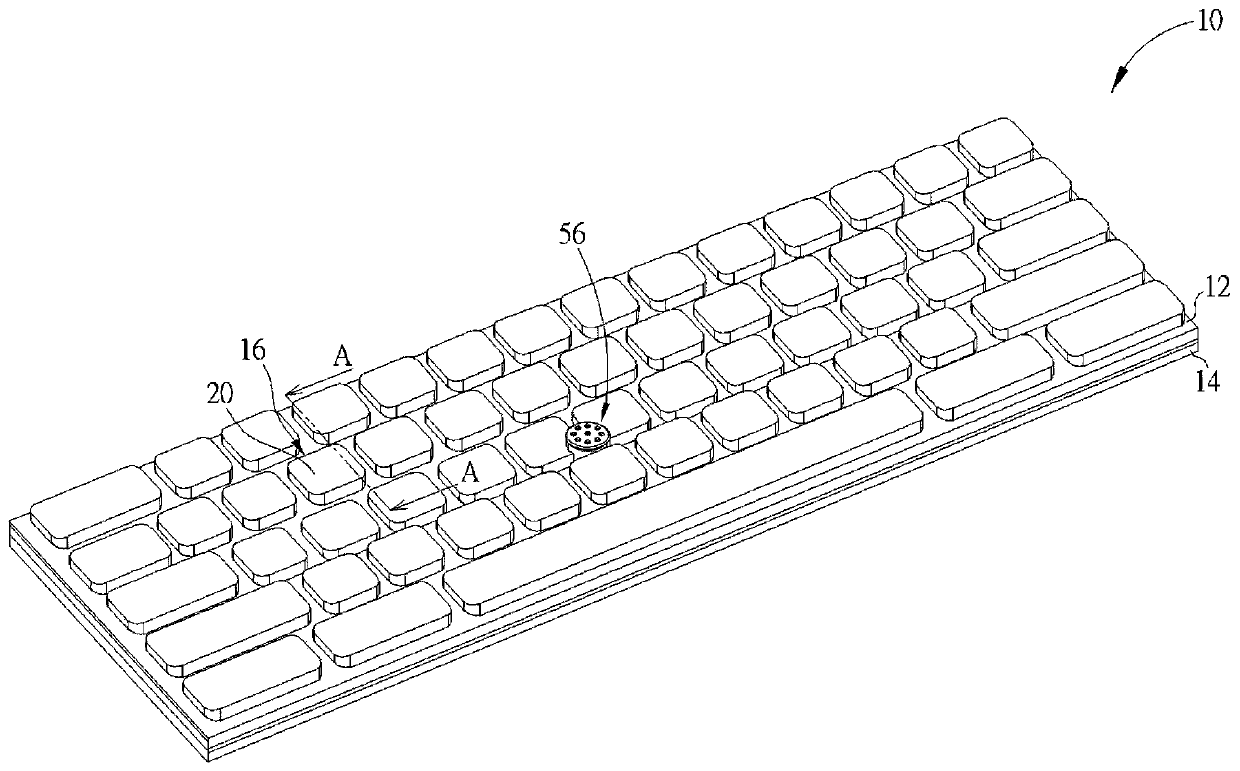
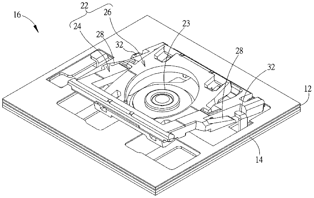
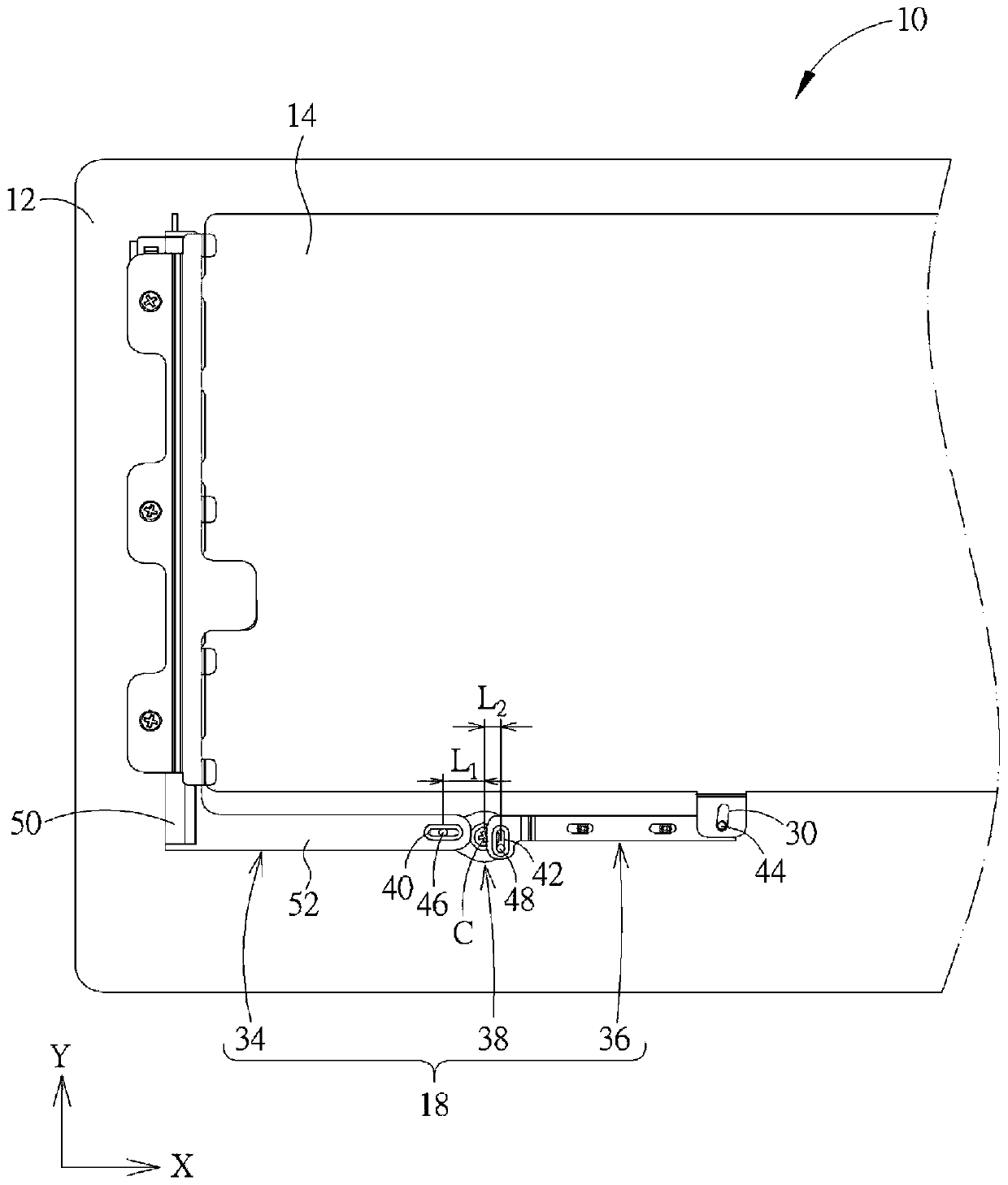
[0054] see figure 1 , figure 2 ,as well as image 3 , figure 1 It is a three-dimensional schematic diagram of the keyboard 10 proposed according to an embodiment of the present invention, figure 2 for figure 1 The enlarged schematic diagram of the middle key 16, image 3 for figure 1 Partially enlarged schematic view of the middle keyboard 10 from another perspective, wherein in order to clearly show the internal structure of the key 16, figure 2 The illustration of the keycap 20 is omitt...


PUM


Abstract

The invention relates to a keyboard, which comprises an upper bottom plate, a lower bottom plate, keys and a connecting rod mechanism, wherein the keys are arranged on the upper bottom plate; the lower bottom plate is slidably arranged below the upper bottom plate and provided with fixed structural members; the connecting rod mechanism includes a first connecting rod, a second connecting rod and afirst cam member; the first connecting rod is provided with a first sliding slot portion and movably arranged below the upper bottom plate; the second connecting rod is movably arranged below the upper bottom plate and provided with a second sliding slot portion and a driving shaft portion penetrating through the lower bottom plate; the first cam member is pivoted below the upper bottom plate andprovided with a first cam shaft and a second cam shaft which respectively penetrate through the first sliding slot portion and the second sliding slot portion, and the distance between the first camshaft and a first axis of the first cam member is greater than the distance between the second cam shaft and the first axis; and when the first connecting rod slides to a folding position, the first connecting rod rotates the first cam member so as to drive the second connecting rod, and the second connecting rod drives the lower bottom plate to slide so as to enable the fixed structural members to press the keys to drop to a folding height. The connecting rod mechanism of the keyboard can drive a key cap to drop to the folding height with less effort.

Description

technical field [0001] The present invention relates to a keyboard, in particular to a keyboard which uses a link mechanism to drive the key caps of the keys down to the folded height in a labor-saving manner. Background technique [0002] As far as the current usage habits of notebook computers are concerned, the keyboard is one of the indispensable input devices for inputting characters, symbols or numbers. Recently, due to the thinning trend of the notebook computer, the keyboard used in the notebook computer also needs to be thinned. [0003] The traditional keyboard adopts a press design in which the assembly structure of the scissor foot support device and the elastic body is arranged between the keycap and the bottom plate, so that when the keycap is pressed by the user, the elastic body provides elastic restoring force to the keycap to drive The keycap returns to the position before pressing along with the mechanism action of the scissor foot support device. Howeve...

Claims


Application Information

Patent Timeline
Patent Type & Authority Patents(China)
IPC IPC(8): H01H13/705H01H3/12
CPCH01H3/125H01H13/705H01H2221/016
Inventor 苏政敏骆弘杰
Owner DARFON ELECTRONICS (SUZHOU) CO LTD
Why Eureka
Try Eureka