keyboard

A keyboard and keycap technology, applied in electrical components, electrical switches, circuits, etc., can solve the problems of large key height space, damage to the display screen, and the need for considerable thrust, reducing the overall height and solving the problem of excessive thrust Effect

Active Publication Date: 2020-08-18
DARFON ELECTRONICS (SUZHOU) CO LTD +1
View PDF4 Cites 0 Cited by
  • Summary
  • Abstract
  • Description
  • Claims
  • Application Information

AI Technical Summary

Problems solved by technology

However, due to the cross pivot design of the scissors support adopted by the above-mentioned scissors support device, the key needs a large height space, so when the upper cover and the lower case of the notebook computer are folded, in order to avoid being arranged on the lower case The keycap on the body damages the display screen arranged on the upper cover, and there is often a gap between the upper cover and the lower casing to accommodate the keycap, which will limit the appearance and size design of the notebook computer, and is not conducive to the design of the notebook computer. Thin design
[0004] In order to solve the above problems, a lower base plate is usually arranged under the upper base plate of the keyboard. The lower base plate can slide horizontally relative to the upper base plate and a fixed structural member is formed at the position of the scissor foot support corresponding to each key. When the base plate slides to the retracted position relative to the upper base plate, each fixed structural member will push the scissor foot support of the corresponding key to pivot downward, so that the key cap sinks to avoid the above-mentioned damage to the display screen. However, since the number of keys on the keyboard is at least nearly a hundred, the operation of driving the bottom plate to control the lifting of each keycap on the keyboard will require a considerable thrust. Main issues in keycap lift design

Method used


Image

  • keyboard
  • keyboard
  • keyboard

Examples


Embodiment Construction

[0030] The following descriptions of the various embodiments refer to the accompanying drawings to illustrate specific embodiments in which the present invention can be practiced. The directional terms mentioned in the present invention, such as "upper", "lower", "front", "rear", "left", "right", "side", etc., are only referring to the directions of the attached drawings. Therefore, the directional terms used are used to illustrate and understand the present invention, but not to limit the present invention.

[0031] In the following embodiments, the same parts are denoted by the same symbols in different drawings.

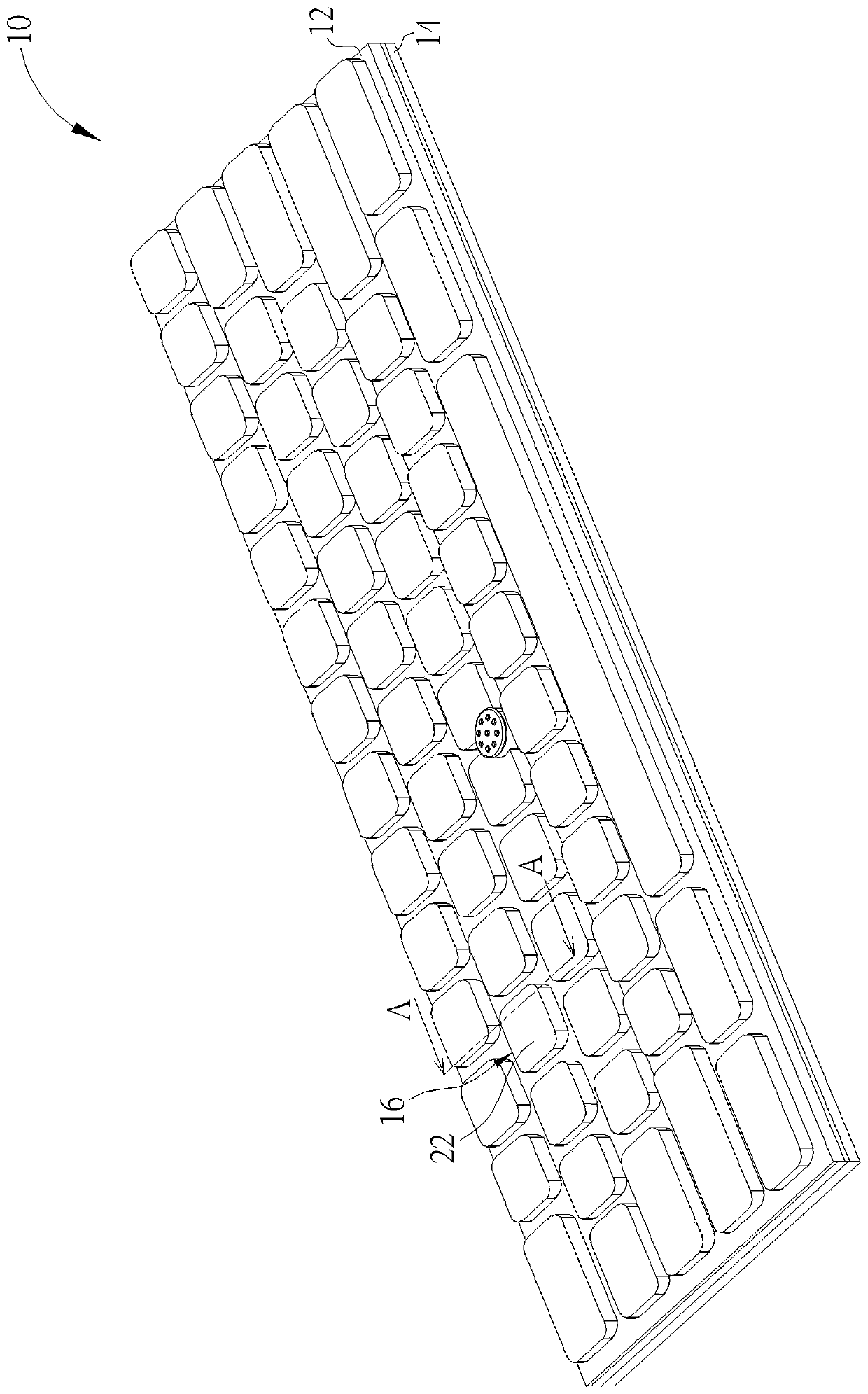
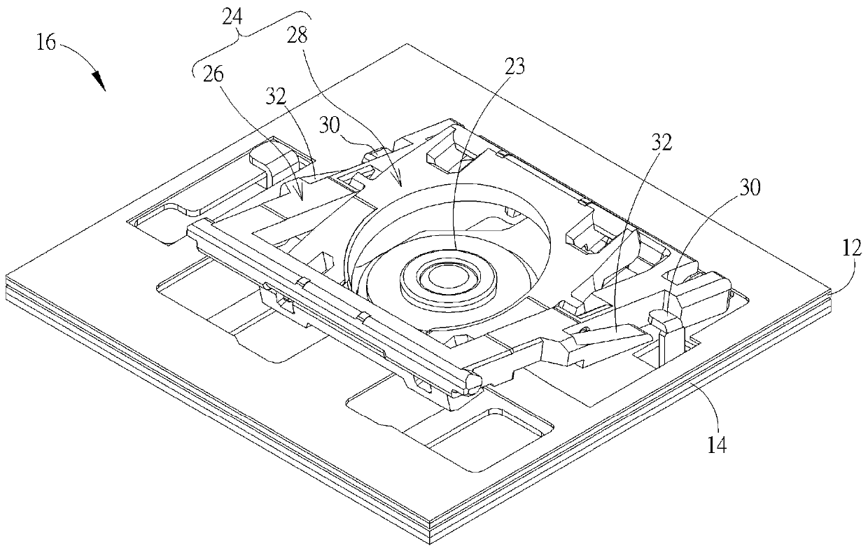
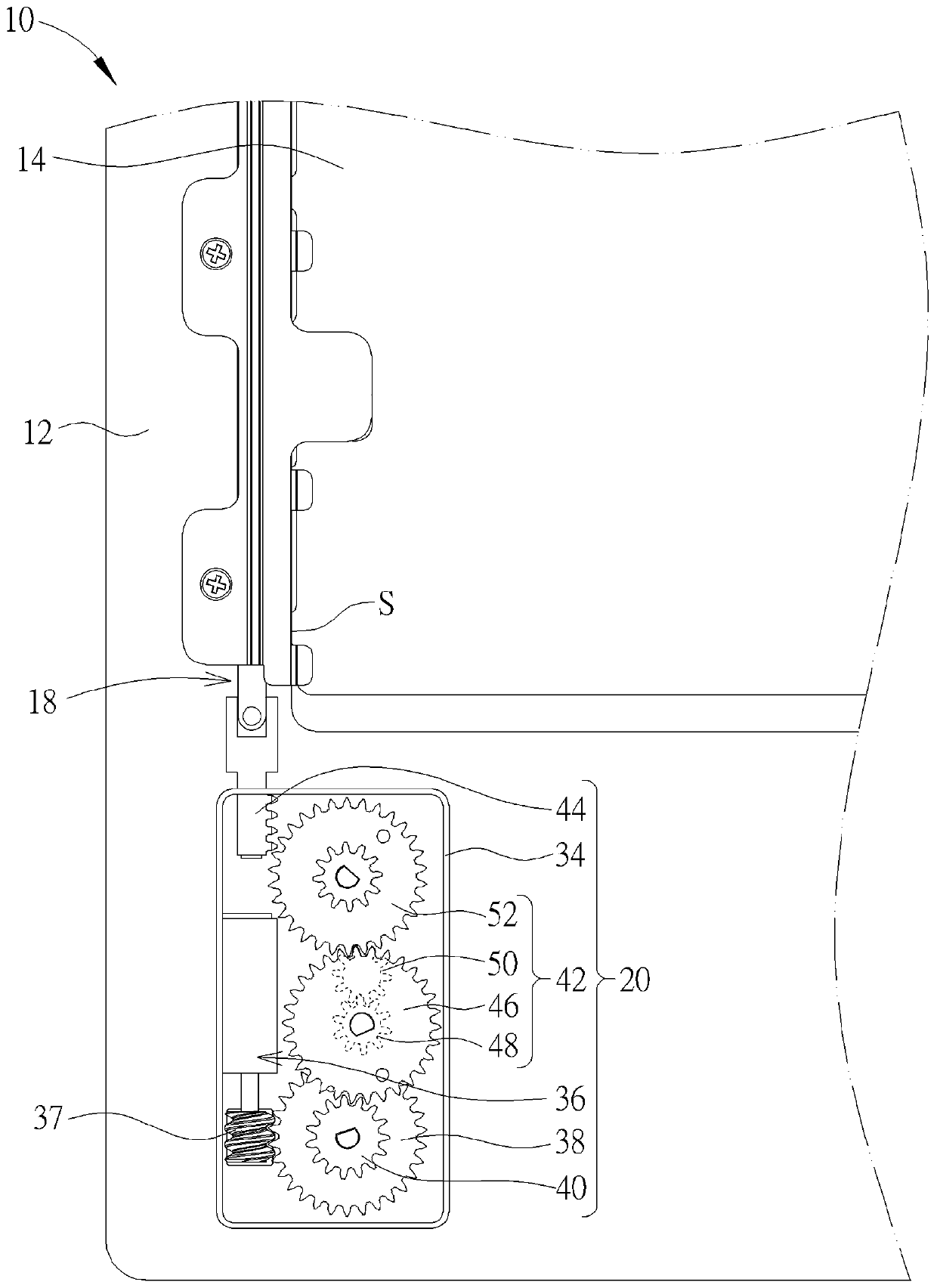
[0032] see figure 1 , figure 2 as well as image 3 , figure 1 It is a three-dimensional schematic diagram of the keyboard 10 proposed according to an embodiment of the present invention, figure 2 for figure 1 The enlarged schematic diagram of the button 16, image 3 for figure 1 Partially enlarged schematic diagram of the keyboard 10 in another perspecti...


PUM


Abstract

The invention discloses a keyboard. The keyboard comprises an upper bottom plate, keys, a lower bottom plate slidingly arranged below the upper bottom plate and having a fixed structural member, a drive motor mechanism and a connection rod mechanism connected with the lower bottom plate and movably arranged below the upper bottom plate. The drive motor mechanism is connected with the connection rod mechanism and comprises a shell, a drive motor arranged in the shell and having a screw rod, a first concentric gear, a second concentric gear and a rack rod. The first concentric gear is pivoted with the internal portion of the shell and engaged with the screw rod. The diameter of the first concentric gear is larger than the diameter of the second concentric gear. The rack rod is connected withthe connection rod mechanism and is connected with the first concentric gear through the second concentric gear. When the drive motor drives the screw rod to rotate to drive the rack rod through thefirst and second concentric gears, the rack rod drives sliding of the lower bottom plate through the connection rod mechanism to allow the fixed structural member to compress the keys to go down. Thekeyboard facilitates thin design of a portable electronic device and effectively solves the problem that the keycaps damage the display screen in the prior art.

Description

technical field [0001] The invention relates to a keyboard, in particular to a keyboard which uses a driving motor mechanism to drive the key caps of the keys down to the folded height with labor-saving. Background technique [0002] As far as the current usage habits of notebook computers are concerned, the keyboard is one of the indispensable input devices for inputting characters, symbols or numbers. Recently, due to the thinning trend of notebook computers, there is also a demand for thinner keyboards used in notebook computers. [0003] The traditional keyboard adopts a press design that uses the assembly structure of the scissor foot support device and the elastic body to be arranged between the keycap and the bottom plate, so that when the keycap is pressed by the user, the elastic body provides elastic recovery force to the keycap to drive The keycap returns to the position before pressing along with the mechanism action of the scissor foot support device. However,...

Claims


Application Information

Patent Timeline
Patent Type & Authority Patents(China)
IPC IPC(8): H01H13/70H01H13/14
CPCH01H13/14H01H13/70
Inventor 苏政敏
Owner DARFON ELECTRONICS (SUZHOU) CO LTD
Why Eureka
Try Eureka