led constant current drive module

A driving module and error amplifier technology, applied in the use of semiconductor lamps, electroluminescent light sources, electric light sources, etc., can solve the problems of small occupancy, affecting the linearity of output current, etc., and achieve the effect of improving the input PWM dimming frequency

Active Publication Date: 2020-08-25
QX MICRO DEVICES
View PDF3 Cites 0 Cited by
  • Summary
  • Abstract
  • Description
  • Claims
  • Application Information

AI Technical Summary

Problems solved by technology

[0006] The technical characteristics and disadvantages of the traditional technology are: the traditional LED linear constant current module, when performing PWM dimming, the EA amplifier module needs a certain settling time from shutdown to startup, and this time will affect the linearity of the output current. Especially when the PWM frequency is high or the duty ratio is small, it is more obvious

Method used


Image

  • led constant current drive module
  • led constant current drive module
  • led constant current drive module

Examples


Embodiment Construction

[0033] The present invention will be described in further detail below in conjunction with accompanying drawing:

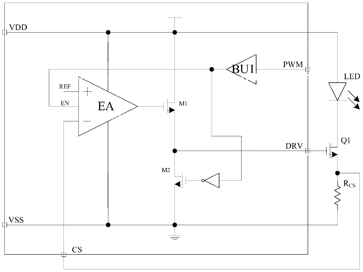
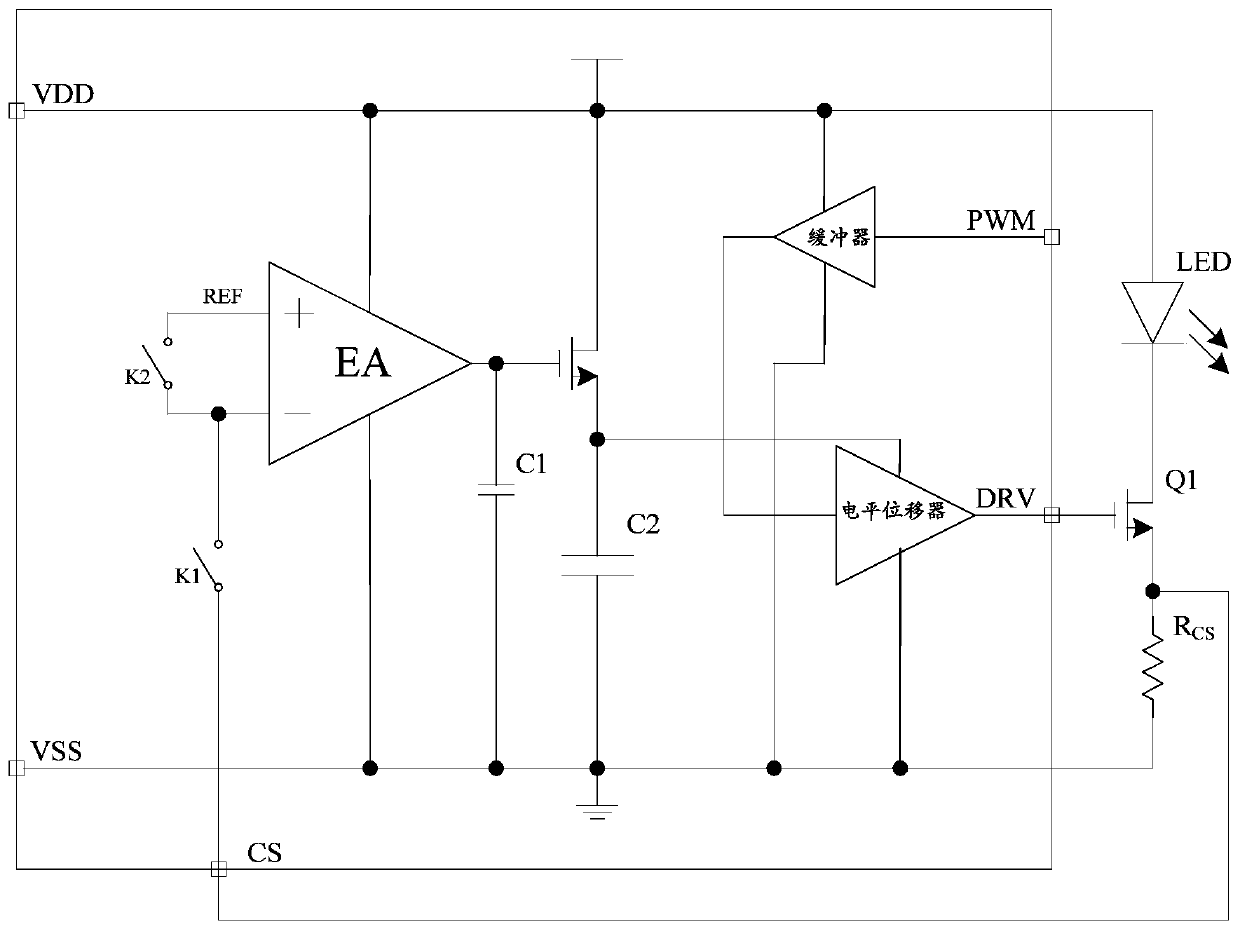
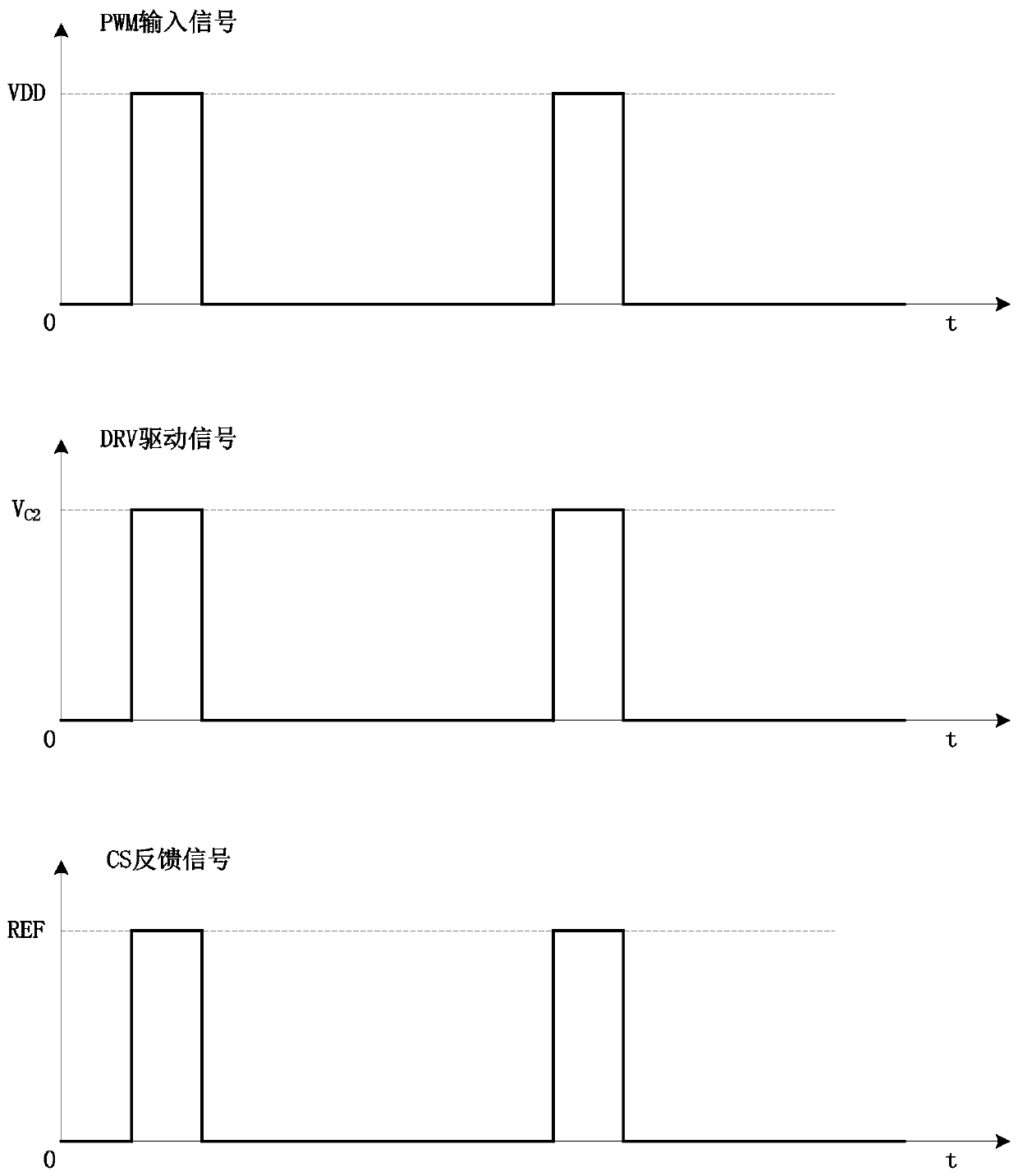
[0034] figure 2 , image 3 A first embodiment of the invention is shown.

[0035] see figure 2 , image 3 As shown, the LED constant current drive module includes an error amplifier, a first switch, a second switch, a first capacitor and a second capacitor, a buffer and a level shifter; the first capacitor and the second capacitor connected in parallel, and connected to the signal output end of the error amplifier; the first end of the first switch is connected to the signal detection input end of the error amplifier, and the second end of the first switch is connected to the signal of the error amplifier detection terminal, the signal detection terminal of the error amplifier is used to detect the output signal of the dimming current sampling resistor; the first terminal of the second switch is connected to the reference signal input terminal of the error a...


PUM


Abstract

The present invention relates to an LED constant current drive module, comprising an error amplifier, a first switch, a second switch and a signal stabilization module; the first end of the first switch is connected to the signal detection input end of the error amplifier, and the first The second end of a switch is connected to the signal detection end of the error amplifier, and the signal detection end of the error amplifier is used to detect the output signal of the dimming resistor; the first end of the second switch is connected to the error amplifier The reference signal input end of the second switch, the second end of the second switch is connected to the signal detection input end of the error amplifier; the signal stabilization module is connected to the signal output end of the error amplifier, and the error amplifier is in the When the dimming signal input terminal of the error amplifier is at a high level, the first switch is controlled to be turned on, the second switch is controlled to be turned off, and the signal stabilization module outputs a first constant signal.

Description

technical field [0001] The invention relates to a dimming device, in particular to an LED constant current drive module. Background technique [0002] With the advancement of technology, the dimming needs of LED lamps and laser LED lamps are becoming more and more obvious. Since PWM dimming has the characteristic of not changing the spectral wavelength, a good PWM dimming LED constant current driver chip is easier to be accepted by the market. ! [0003] figure 1 Shown in is an ordinary LED linear constant current drive module. This module detects the voltage on the RCS resistor through the CS pin, inputs it to the chip (error amplifier) ​​EA module, compares and amplifies it with the reference voltage, outputs a constant DRV voltage, and then makes the output LED lamp constant current; input through the PWM pin PWM square wave signal, and then modulate the brightness of the output LED light to achieve the desired effect. [0004] In the traditional LED linear constant c...

Claims


Application Information

Patent Timeline
Patent Type & Authority Patents(China)
IPC IPC(8): H05B45/345H05B45/325H05B45/395H05B44/00
CPCH05B45/00Y02B20/30
Inventor 李剑
Owner QX MICRO DEVICES
Why Eureka
Try Eureka