Device for mutual support of two construction members

A component and support tube technology, applied in the field of devices where two components support each other, to achieve the effect of improving deformation resistance

Inactive Publication Date: 2002-10-23
武尔夫·舒伯特 +1
View PDF2 Cites 1 Cited by
  • Summary
  • Abstract
  • Description
  • Claims
  • Application Information

AI Technical Summary

Problems solved by technology

However, the pressure that can be transmitted through this tensioning element must be limited to avoid overloading of the lining

Method used


Image

  • Device for mutual support of two construction members
  • Device for mutual support of two construction members
  • Device for mutual support of two construction members

Examples


Embodiment Construction

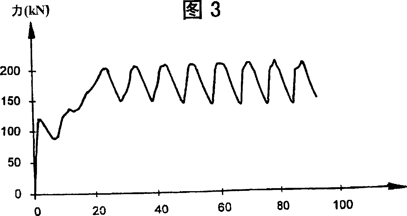
[0013] Fig. 3 corresponds to the tension characteristic of the device of the present invention figure 2 curve.

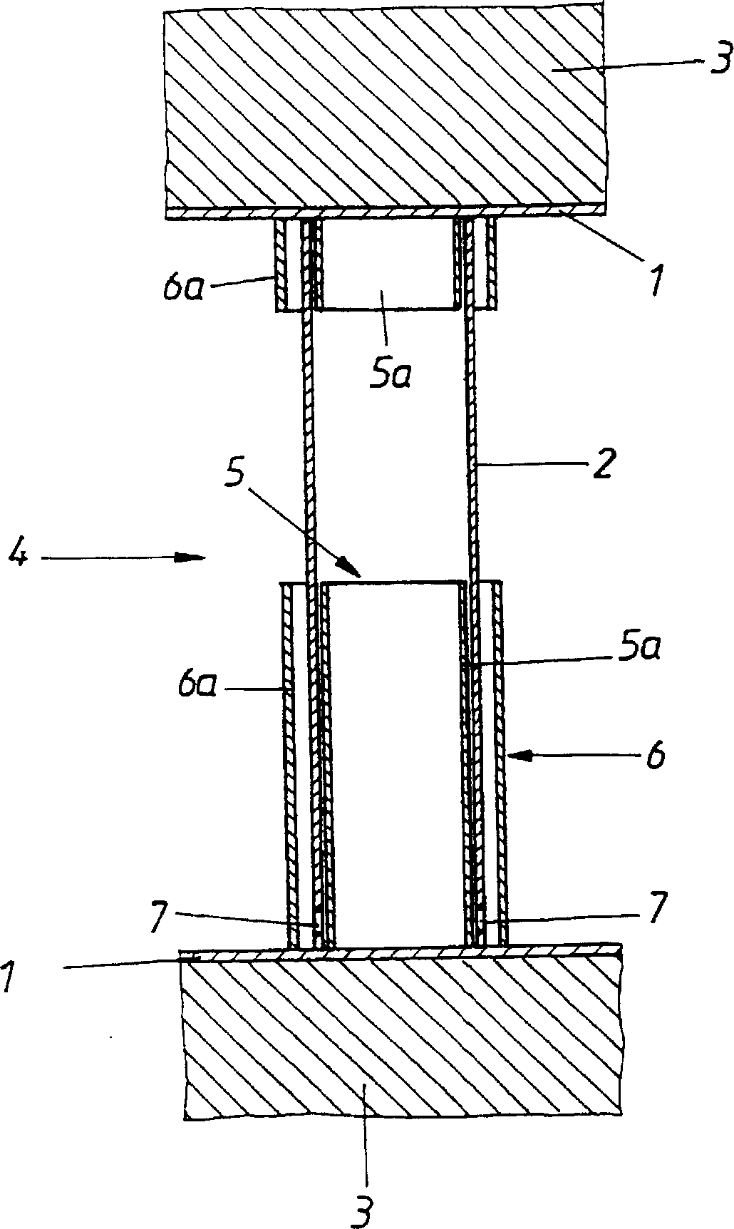
[0014] The device according to the invention according to the exemplary embodiment shown essentially consists of two pressure transmission plates 1 between which a tensioning tube 2 is arranged. The section 3 of the tunnel lining is supported by this tensioning tube 2 , and the tunnel lining is divided into sections 3 by contraction joints 4 running longitudinally in the tunnel. As a difference from known devices of this type, the tensioning tube 2 is arranged according to the invention concentrically between an inner support tube 5 and an outer support tube 6, which are divided into two sections 5a or 6a. These pipe sections 5 a and 6 a are respectively connected to one of the two pressure transmission plates 1 . In the area of ​​the lower end edge of the tensioning tube 2 , holes 7 are provided on the tensioning tube, which, due to the weakening of the cross se...


PUM


Abstract

A device for supporting two constructional elements against each other consisting of at least one upset tube arranged between pressure transmitting plates located at the ends of the tube for the purpose of limiting inward and outward bulging. The upset tube is coaxially arranged between two supporting tubes having a smaller length than the upset tube of which the external supporting tube encloses the upset tube at a radial distance.

Description

technical field [0001] The invention relates to a device for the mutual support of two components, consisting of at least one tensioning tube arranged between pressure transmission plates on the front side. Background technique [0002] In order to be able to control the large deformations that occur when tunneling in harsh mountainous regions, it is known that the tunnel lining (Tunnelauskleidung) is divided into many sections by shrinkage joints distributed along the tunnel longitudinal The shrink joint lining still has the corresponding support (Ausbauwiderstand) resistance. However, the pressure which can be transmitted via this tensioning element must be limited to a certain extent in order to avoid overloading of the lining. In order to achieve a corresponding compaction resistance within the required compaction stroke, tensioning elements in the form of tensioning tubes have been used which are tensioned in the direction of the end faces between the two pressure tran...

Claims


Application Information

Patent Timeline
Patent Type & Authority Patents(China)
IPC IPC(8): B60R19/34F16F7/12E21D11/08E21D11/04
CPCB60R19/34E21D11/083F16F7/12F16F2230/0052
Inventor 武尔夫·舒伯特贝恩德·莫里茨
Owner 武尔夫·舒伯特
Why Eureka
Try Eureka