Composite ion-exchange membrane

Inactive Publication Date: 2006-10-26
TOYO TOYOBO CO LTD
View PDF12 Cites 44 Cited by
  • Summary
  • Abstract
  • Description
  • Claims
  • Application Information

AI Technical Summary

Benefits of technology

[0018] As a result, the present inventors found out that it is possible to obtain a composite ion exchange membrane having a high swelling resistance and being superior in mechanical strength and ion conductivity by impregnating a support membrane having continuous pores penetrating the membrane with an ion exchange resin composition containing an aromatic polyether and/or its derivative, the aromatic polyether being obtained by polymerizing a specific raw material.
[0019]

Problems solved by technology

However, because membranes comprising perfluorocarbon sulfonic acid polymer soften up at temperatures of 100° C. or higher, the operating temperature of fuel cells using such membranes is limited to 80° C. or lower.
It is however difficult to control sulfonation reactions by this method.
In some cases, therefore, it is impossible to adjust the degree of sulfonation to a desired degree or problems such as gelation are caused by nonuniform sulfonation or side reactions.
Hydrocarbon-based solid polymer electrolytes including the above-mentioned suflonic acid group-introduced polysulfone have problems with respect to water resistance under high humidity because they are more prone to hydration or swelling in comparison to membranes containing perfluorocarbon sulfonic acid polymers.
All the above techniques, however, can inhibit swelling, but they are problematic in that ionizable groups lose their ionicity through the crosslinking reaction and, as a result, ion conductivity falls.
Such solid polymer electrolyte membranes, however, did not exhibit satisfactory characteristics as fuel cells because their polymer skeleton itself was poor in durability.
The crosslinking reaction of this technique, however, requires a catal

Method used

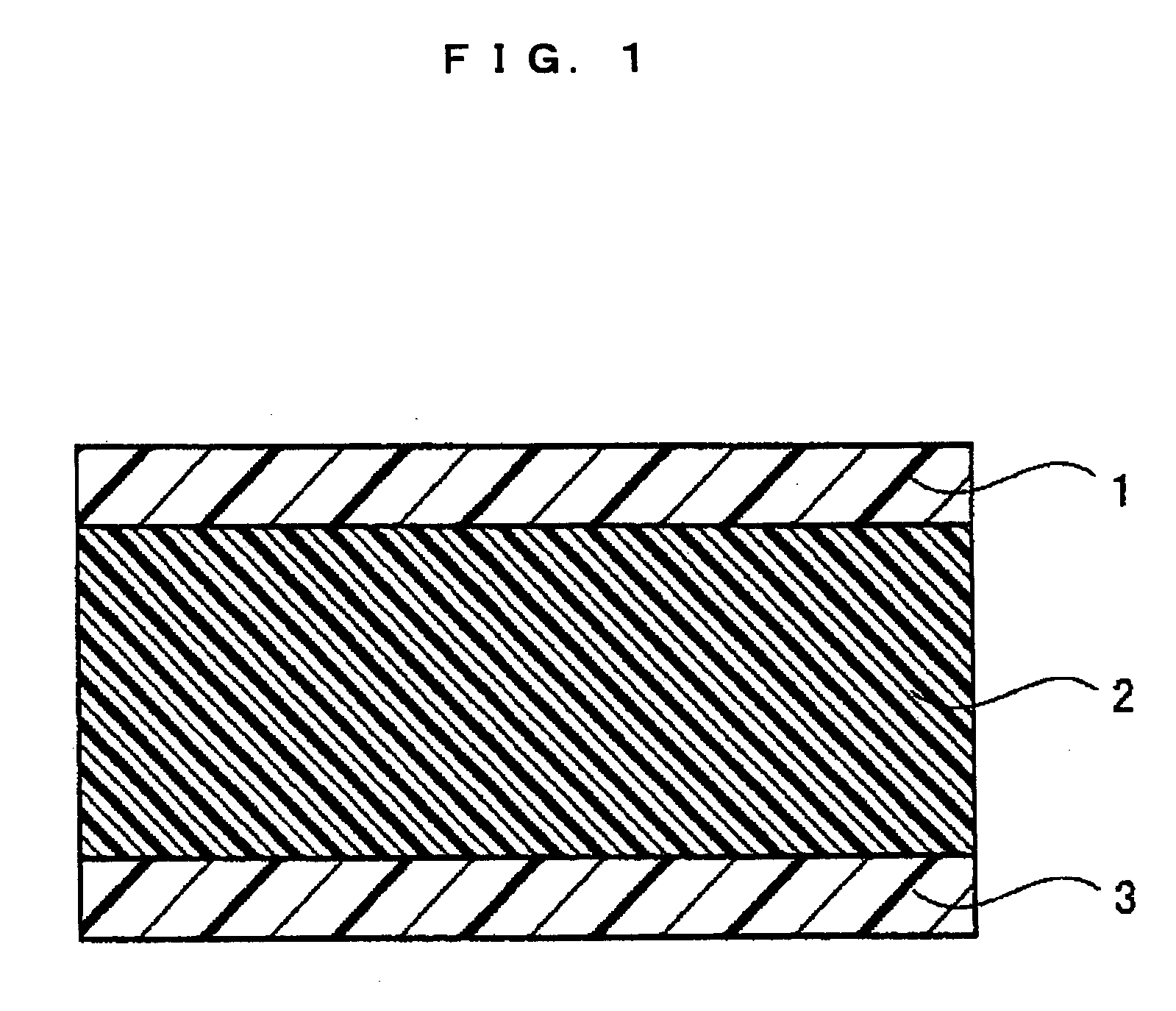

Image

  • Composite ion-exchange membrane
  • Composite ion-exchange membrane
  • Composite ion-exchange membrane

Examples


synthesis example 1

(i) Synthesis Example 1

[0234] First, 12.28 g (25.0 mmol) of sodium 4,4′-dichlorodiphenylsulphone-3,3′-disulfonate, 7.18 g (25.0 mmol) of 4,4′-chlorodiphenylsulfone, 9.31 g (50.0 mmol) of 4,4′-biphenol, 7.95 g (57.5 mmol) of potassium carbonate, 100 ml of N-methyl-2-pyrrolidone and 15 ml of toluene were charged into a 200 ml side-arm flask equipped with a nitrogen introduction tube, a stirring blade, a Dean-Stark trap and a thermometer and then were heated under nitrogen flow while being stirred on an oil bath.

[0235] Subsequently, after dehydration by azeotropy with toluene was conducted at 140° C., toluene was removed completely by distillation. Thereafter the temperature was raised to 200° C. and heating was continued for 15 hours. Subsequently, the solution cooled to room temperature was poured into 2000 ml of pure water. Thus, ion exchange resin was reprecipitated. Then, the ion exchange resin filtered was dried under reduced pressure at 50° C. to yield the ion exchange resin of...

synthesis examples 2 to 12

(ii) Synthesis Examples 2 to 12

[0236] The ion exchange resins of Synthesis Examples 2 to 12 were synthesized in the same manner as Example 1, with the exception that the kinds and molar ratios of monomers were changed as shown in Table 1. The yields and the measurements of inherent viscosity of the ion exchange resin are also shown in Table 1.

TABLE 1Charge amount of monomer (mmol)InherentS-YieldviscosityDCDPSDCBNDCDPSBPBPF(%)(dl / g)Synthesis25—2550—950.95Example 1Synthesis30—2050—930.83Example 2Synthesis35—1550—900.77Example 3Synthesis25—25—50910.54Example 4Synthesis35—15—50890.53Example 5Synthesis40—10—50850.59Example 6Synthesis2030—50—930.88Example 7Synthesis2525—50—910.91Example 8Synthesis3020—50—840.79Example 9Synthesis15—3550—970.94Example 10Synthesis18—32—50980.55Example 11Synthesis133750—960.91Example 12

S-DCDPS: sodium 4,4′-dichlorodiphenylsulfone-3,3′-disulfonate

DCBN: 2,6-dichlorobenzonitrile

DCDPS: 4,4′-dichlorodiphenylsulfone

BP: 4,4′-biphenol

BPF: 9,9-bis(4-hydroxypheny...

example 1

[0238] First, an isotropic solution with a poly(p-phenylene-cis-benzobisoxazole) concentration of 1% by mass was prepared by diluting a dope comprising polyphosphoric acid containing 14% by mass of poly(p-phenylene-cis-benzobisoxazole) polymer having an intrinsic viscosity of 25 dL / g by addition of methane sulfonic acid.

[0239] Then, this solution was formed into a film on a glass plate heated to 90° C. at a film formation rate of 5 mm / sec using an applicator with a clearance of 300 μm. The dope film formed on the glass plate was placed as it was in a thermohygrostat at 25° C. and 80% RH and was solidified for one hour. The resulting film was washed with water until the washings exhibited pH 7±0.5, yielding a support membrane.

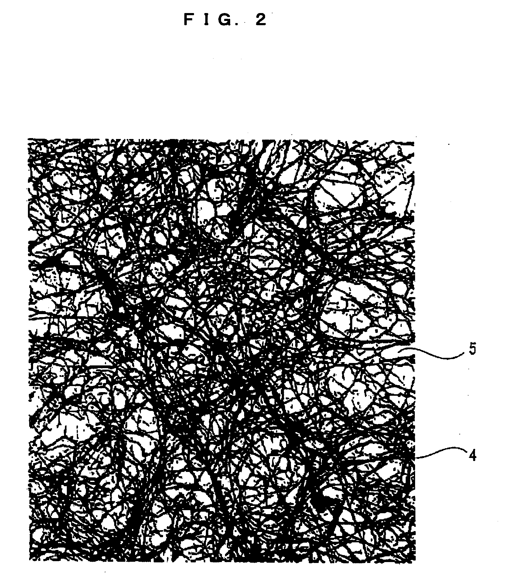
[0240] Subsequently, the surface morphology observation by an atomic force microscope and the section morphology observation by a transmission electron microscope of the resulting support membrane confirmed that the membrane was a porous membrane with continuo...


PUM

PropertyMeasurementUnit
Fractionaaaaaaaaaa
Fractionaaaaaaaaaa
Fractionaaaaaaaaaa

Abstract

A composite ion exchange membrane having a high swelling resistance and being superior in mechanical strength and ion conductivity can be provided by means of an composite ion exchange membrane including an ion exchange resin composition and a support membrane having a continuous pore penetrating the support membrane, wherein the support membrane is one which accepts the ion exchange resin composition within the pore, and wherein the ion exchange resin composition is one which contains an ion exchange resin containing, as a main component, an aromatic polyether and/or its derivative, the aromatic polyether being obtained by mixing a compound having a specific structure, an aromatic dihalogenated compound and a bisphenol compound with a carbonate and/or a bicarbonate of an alkali metal and polymerizing the mixture in an organic solvent.

Description

TECHNICAL FIELD [0001] The present invention relates to a composite ion exchange membrane. Specifically, the present invention relates to a composite ion exchange membrane superior in both mechanical strength and ion conductivity (proton conductivity). BACKGROUND ART [0002] In recent years, much attention has been focused on novel power generating techniques which are superior in energy efficiency or environmental friendliness. In particular, solid polymer fuel cells using solid polymer electrolyte membranes are characterized as exhibiting high energy density and being started and stopped more easily than fuel cells of other systems due to their lower operating temperature. Therefore, they are on development as generators for electric motorcars, dispersed power generation and the like. In addition, development of direct methanol fuel cells which use solid polymer electrolyte membranes and into which methanol is supplied directly as fuel are underway for applications such as electric...

Claims


Application Information

Patent Timeline
IPC IPC(8): C08J5/20C08J5/22H01M8/02
CPCH01M8/0291H01M2300/0082C08J2381/06Y02E60/50C08J5/2256H01M2300/0094H01M8/0289
Inventor KITAMURA, KOTASAKAGUCHI, YOSHIMITSUNAGAHARA, SHIGENORIHAMAMOTO, SHIROTAKIMOTO, NAOHIKOSUGIHARA, HIDEKITAKASE, SATOSHIKITAGAWA, TOORUNOSHIRO, MIYAKO
Owner TOYO TOYOBO CO LTD
Why Eureka
Try Eureka