
Conveying line body

A technology of conveying line and line body, applied in the direction of conveyor, transportation and packaging, can solve the problem of inability to change the conveying rate, and achieve the effect of solving the conveying rate

Inactive Publication Date: 2019-02-19
ZHUHAI GREE INTELLIGENT EQUIP CO LTD +1
View PDF5 Cites 0 Cited by
  • Summary
  • Abstract
  • Description
  • Claims
  • Application Information

AI Technical Summary

Problems solved by technology

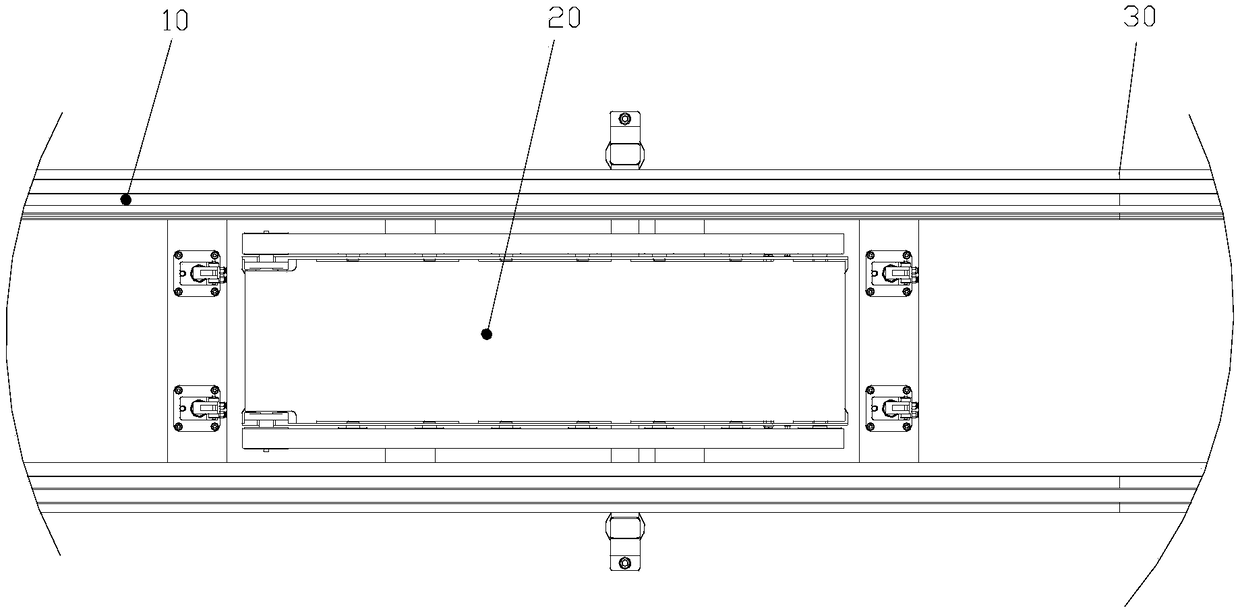
[0003] The main purpose of the present invention is to provide a conveying line body to solve the problem that the conveying line body in the prior art cannot change the conveying rate

Method used


Image

  • Conveying line body
  • Conveying line body

Examples


Embodiment Construction

[0020] It should be noted that, in the case of no conflict, the embodiments in the present application and the features in the embodiments can be combined with each other. The present invention will be described in detail below with reference to the accompanying drawings and examples.

[0021] It should be pointed out that the following detailed description is exemplary and intended to provide further explanation to the present application. Unless defined otherwise, all technical and scientific terms used herein have the same meaning as commonly understood by one of ordinary skill in the art to which this application belongs.

[0022] It should be noted that the terminology used here is only for describing specific implementations, and is not intended to limit the exemplary implementations according to the present application. As used herein, unless the context clearly dictates otherwise, the singular is intended to include the plural, and it should also be understood that wh...


PUM


Abstract

The invention provides a conveying line body. The conveying line body comprises a main conveying line body and an auxiliary conveying line body, wherein the main conveying line body is used for conveying a preset part, the main conveying line body is provided with a feeding port which is used for feeding the preset part and a discharging port which is used for sending out the preset part; and theauxiliary conveying line body is located between the feeding port and the discharging port, the conveying speed of the auxiliary conveying line body is adjustable, so that the auxiliary conveying linebody is used for adjusting the moving speed of the preset part when the preset part enters the auxiliary conveying line body from the main conveying line body. According to the conveying line body, the problem that a conveying line body cannot change the conveying speed in the prior art is solved.

Description

technical field [0001] The invention relates to the field of workpiece conveying, in particular to a conveying line body. Background technique [0002] During the production process of the external unit of the air conditioner, the tooling plate can be used to cooperate with the conveying line body. The conveying line bodies in the prior art are all conveying tooling boards at a uniform speed. However, when automatic equipment is introduced, in order to ensure the tact of equipment operation, it is necessary to change the original conveying rate when the product enters and exits the automatic station. However, the existing conveying line body cannot meet the above requirements. Contents of the invention [0003] The main purpose of the present invention is to provide a conveying line body to solve the problem that the conveying line body in the prior art cannot change the conveying rate. [0004] In order to achieve the above object, the present invention provides a conve...

Claims


Application Information

Patent Timeline
Patent Type & Authority Applications(China)
IPC IPC(8): B65G17/26B65G23/30
CPCB65G17/26B65G23/30
Inventor 孙宇刘超余长周
Owner ZHUHAI GREE INTELLIGENT EQUIP CO LTD
Learn More