Cylinder type magnetic separator capable of forcing ore discharging

A drum-type magnetic separator and stand technology, which is applied in the fields of magnetic separation, solid separation, chemical instruments and methods, etc., can solve the problems of poor adaptability, inability to meet the needs of magnetic separation, and lack of adjustment capability, and achieve adaptation to Strong ability, the effect of changing the distribution of the magnetic field and improving the work efficiency

Inactive Publication Date: 2019-02-19
林文怡
View PDF1 Cites 7 Cited by
  • Summary
  • Abstract
  • Description
  • Claims
  • Application Information

AI Technical Summary

Problems solved by technology

[0004] In the prior art: the patent with the authorized publication number of CN 206793893 U discloses a cylindrical magnetic separator capable of forced unloading of ore, including a frame, a tank body installed on the frame, a cylinder body and a forced ore unloading device, The forced ore unloading device is composed of a driving device, a rotating shaft, a skeleton fixedly installed on the rotating shaft, and an ore unloading scraper made of soft polymer materials. One end of the rotating shaft is installed on the frame through a bearing seat. The other end of the rotating shaft is connected with the driving device. The number of the ore unloading scrapers is 2-10. The ore unloading scrapers are fixedly installed on the skeleton and keep soft contact with the barrel of the drum magnetic separator. The magnetic pole spacing does not have the ability to adjust, the adaptability is poor, and it cannot meet different magnetic separation requirements

Method used


Image

  • Cylinder type magnetic separator capable of forcing ore discharging
  • Cylinder type magnetic separator capable of forcing ore discharging
  • Cylinder type magnetic separator capable of forcing ore discharging

Examples


Embodiment Construction

[0045] The following will clearly and completely describe the technical solutions in the embodiments of the present invention with reference to the accompanying drawings in the embodiments of the present invention. Obviously, the described embodiments are only some, not all, embodiments of the present invention. Based on the embodiments of the present invention, all other embodiments obtained by persons of ordinary skill in the art without making creative efforts belong to the protection scope of the present invention.

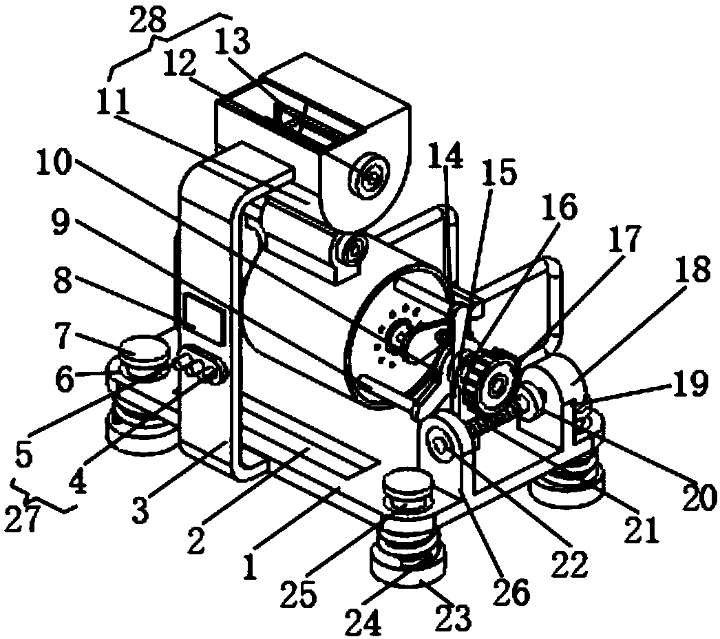
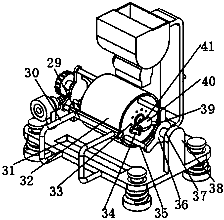
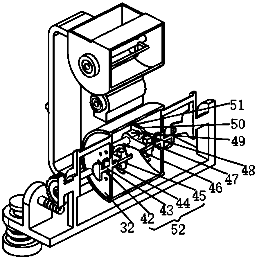
[0046] see Figure 1-4 , the present invention provides a technical solution: a cylindrical magnetic separator capable of forced ore unloading, including a machine base 1, and a live rod 25 is movably connected through the machine base 1;

[0047] There are four groups of live rods 25, and four groups of live rods 25 are arranged side by side in parallel;

[0048] The top of the live rod 25 is fixed with a limit block 7, and the position of the support 1 corr...


PUM


Abstract

The invention discloses a cylinder type magnetic separator capable of forcing ore discharging. The cylinder type magnetic separator comprises a machine base. Moving rods are movably connected to the machine base in a penetrating mode. Four sets of the moving rods are arranged. The four sets of moving rods are arranged in a parallel mode. Limiting blocks are fixed to the top of the moving rods. Limiting grooves are formed in the position, corresponding to the limiting blocks, of the machine base. Supporting feet are fixed to the bottom ends of the moving rods. Damping springs are connected to the moving rods in a sleeving mode. The damping springs are arranged between the supporting feet and the machine base. A mounting bracket is fixed to the lateral face of the machine base. An open source single chip microcomputer and a material coupling device are mounted on the lateral face of the mounting bracket. Materials are placed in a feeding cabin. Operating of a stirring motor is controlledby the open source single chip microcomputer. An output shaft of the stirring motor drives stirring blades to rotate to stir the materials uniformly. Material caking and failing to achieve magnetic separation are avoided. The cylinder type magnetic separator is guaranteed to work normally, and working efficiency of the cylinder type magnetic separator is greatly improved.

Description

technical field [0001] The invention relates to the technical field of drum magnetic separators, in particular to a drum magnetic separator capable of forced ore unloading. Background technique [0002] Magnetic separator is one of the most widely used and highly versatile models in the magnetic separation technology industry. It is suitable for the separation of substances with magnetic differences. Magnetic separators are widely used in mining, environmental protection, wood industry, kiln industry, chemistry, Food and other industries, and for the mining industry, the magnetic separator is suitable for wet or dry magnetic separation of manganese ore, magnetite, pyrrhotite, roasted ore, ilmenite, red limonite and other materials. It is used in the iron removal of coal, non-metallic mines, building materials and other materials. At the same time, the magnetic separator is also used in the magnetic separation of industrial sewage and domestic sewage; [0003] At present, th...

Claims


Application Information

Patent Timeline
Patent Type & Authority Applications(China)
IPC IPC(8): B03C1/10
CPCB03C1/10
Inventor 林文怡张鑫石忠
Owner 林文怡
Why Eureka
Try Eureka