Noise reducing structure for hermetically sealed compressor

A compressor and hermetic technology, applied in rotary piston machines, components of pumping devices for elastic fluids, and rotary piston/oscillating piston pump components, etc., can solve problems such as reducing suction volume efficiency

Inactive Publication Date: 2002-10-30
LG ELECTRONICS INC
View PDF2 Cites 3 Cited by
  • Summary
  • Abstract
  • Description
  • Claims
  • Application Information

AI Technical Summary

Problems solved by technology

[0018] Since the noise-reducing chamber 8c is formed within an angle range of 340° to 350° from the valve plate 10, and the inside of the cylinder 15 is divided into a high-pressure chamber 15a and a low-pressure chamber 15b by the valve plate

Method used


Image

  • Noise reducing structure for hermetically sealed compressor
  • Noise reducing structure for hermetically sealed compressor
  • Noise reducing structure for hermetically sealed compressor

Examples


Embodiment Construction

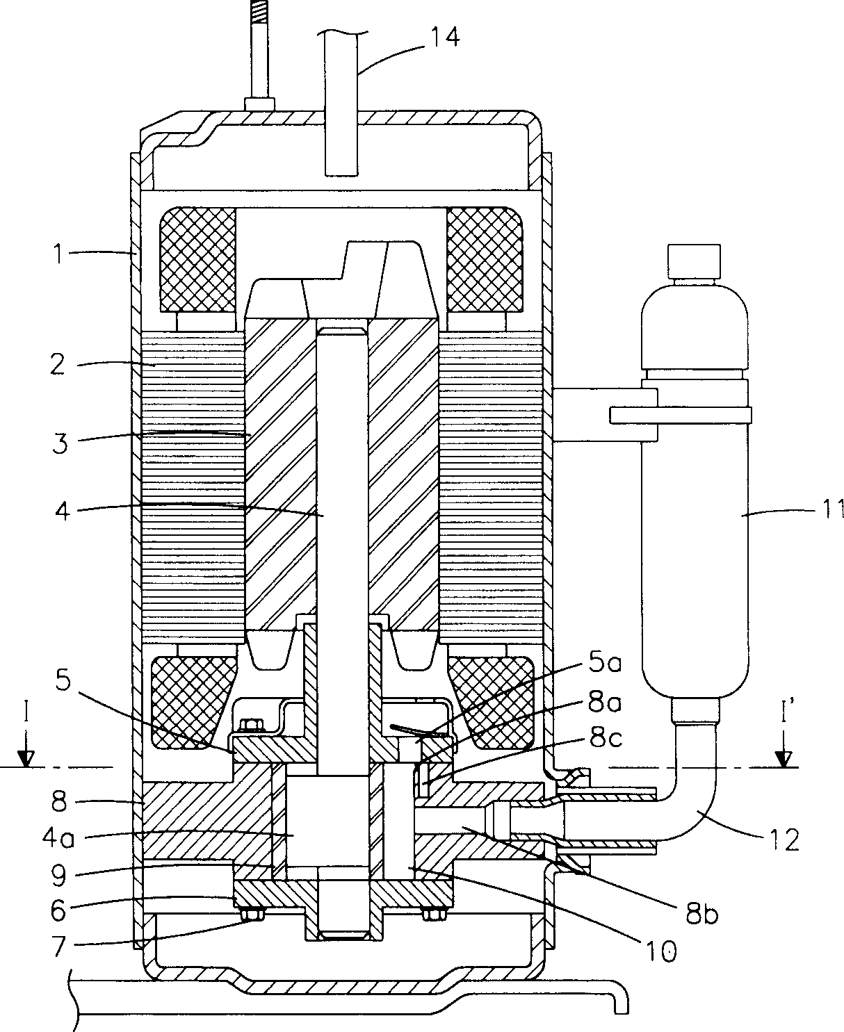
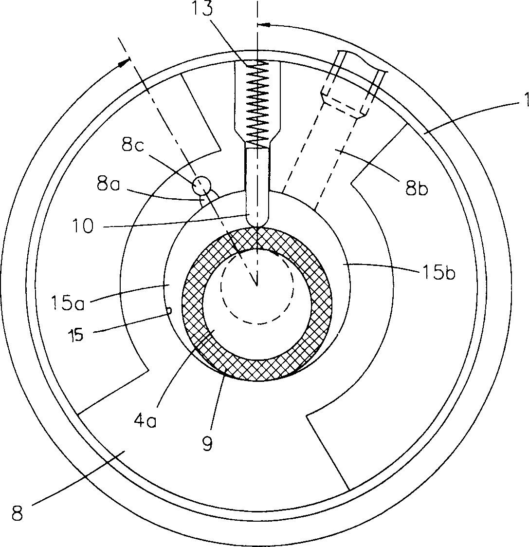
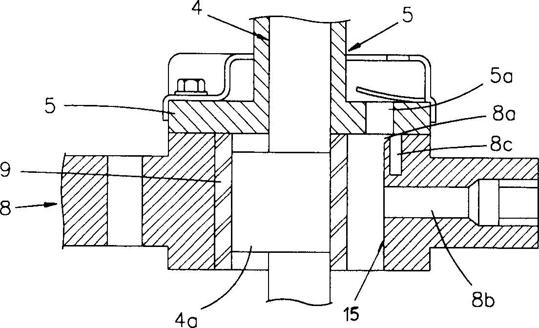
[0033] The noise reduction structure of the hermetic compressor according to the first embodiment of the present invention will be described below with reference to the drawings.

[0034] Such as Figure 4 , 5 Shown in and 6, an upward noise-reducing chamber 108c with a predetermined volume is formed in the cylinder wall of the cylinder 115 at the center of the cylinder block 108 toward the lower bearing 106, and a line communicates with the above-mentioned noise-reducing chamber 108c and The communication passage 108d of the compression chamber of the cylinder 115 .

[0035] The noise-reducing chamber 108c and communication channel 108d formed above are all located at 210°-270° from the position where the radial valve plate 110 divides the interior of the cylinder 115 into a high-pressure chamber 115a and a low-pressure chamber 115b when installed. within the range of angles.

[0036] The upwardly formed noise-reducing chamber 108c has a cylindrical shape, and the ratio of...


PUM


Abstract

A noise-reducing structure of a hermetic compressor, which can effectively reduce the noise in this frequency band caused by the vibration of the compression chamber caused by the pressure shock effect in the cylinder during the compression stroke of the cylinder, and can prevent the reduction Noise reduction in chamber volumetric efficiency. The structure has a noise-reducing chamber with a predetermined volume formed in the above-mentioned cylinder body; and a communication channel for communicating the above-mentioned noise-reducing structure with the above-mentioned cylinder.

Description

technical field [0001] The present invention relates to a structure for reducing noise of a hermetic compressor, more specifically, relates to a structure capable of effectively reducing the frequency band caused by the vibration of the compression chamber due to the pressure impact effect in the cylinder during the compression cycle of the cylinder. Noise, and noise reduction structure that prevents volume efficiency reduction in the noise reduction chamber. Background technique [0002] Such as figure 1 and 2 As shown, a conventional hermetic compressor has a motor having a stator 2, a rotor 3, etc. in a hermetic container 1 of a predetermined volume. [0003] A crankshaft 4 having an eccentric portion 4a at its lower end is installed in the rotor 3, and upper and lower bearings 5 ​​and 6 are respectively connected with bolts 7 to a cylinder block 8 surrounding the lower portion of the crankshaft 4 having the eccentric portion 4a. [0004] A rolling piston 9 is connecte...

Claims


Application Information

Patent Timeline
IPC IPC(8): F04C29/06F04C18/356
Inventor 金政勳秋政旼
Owner LG ELECTRONICS INC
Why Eureka
Try Eureka