Rotary shaft mechanical locking device based on lever micro-motion principle

A technology of mechanical locking and rotating shafts, which is applied in the direction of mechanical equipment, brake parts, brake parts, etc., can solve the problems of easy damage of the locking handle, uneven locking force, and non-adjustable locking force, etc., to eliminate The locking force is uneven, the accuracy is not damaged, and the mechanical index guarantees the effect

Pending Publication Date: 2019-02-22
JIUJIANG PRECISION MEASURING TECH RES INST
View PDF19 Cites 0 Cited by
  • Summary
  • Abstract
  • Description
  • Claims
  • Application Information

AI Technical Summary

Problems solved by technology

[0004] In order to solve the defects such as uneven locking force of the locking device, non-adjustable locking force, easy damage of the locking handle, and poor reliability of the locking device, the present invention provides a locking device using the principle of...

Method used


Image

  • Rotary shaft mechanical locking device based on lever micro-motion principle
  • Rotary shaft mechanical locking device based on lever micro-motion principle

Examples


Embodiment 1

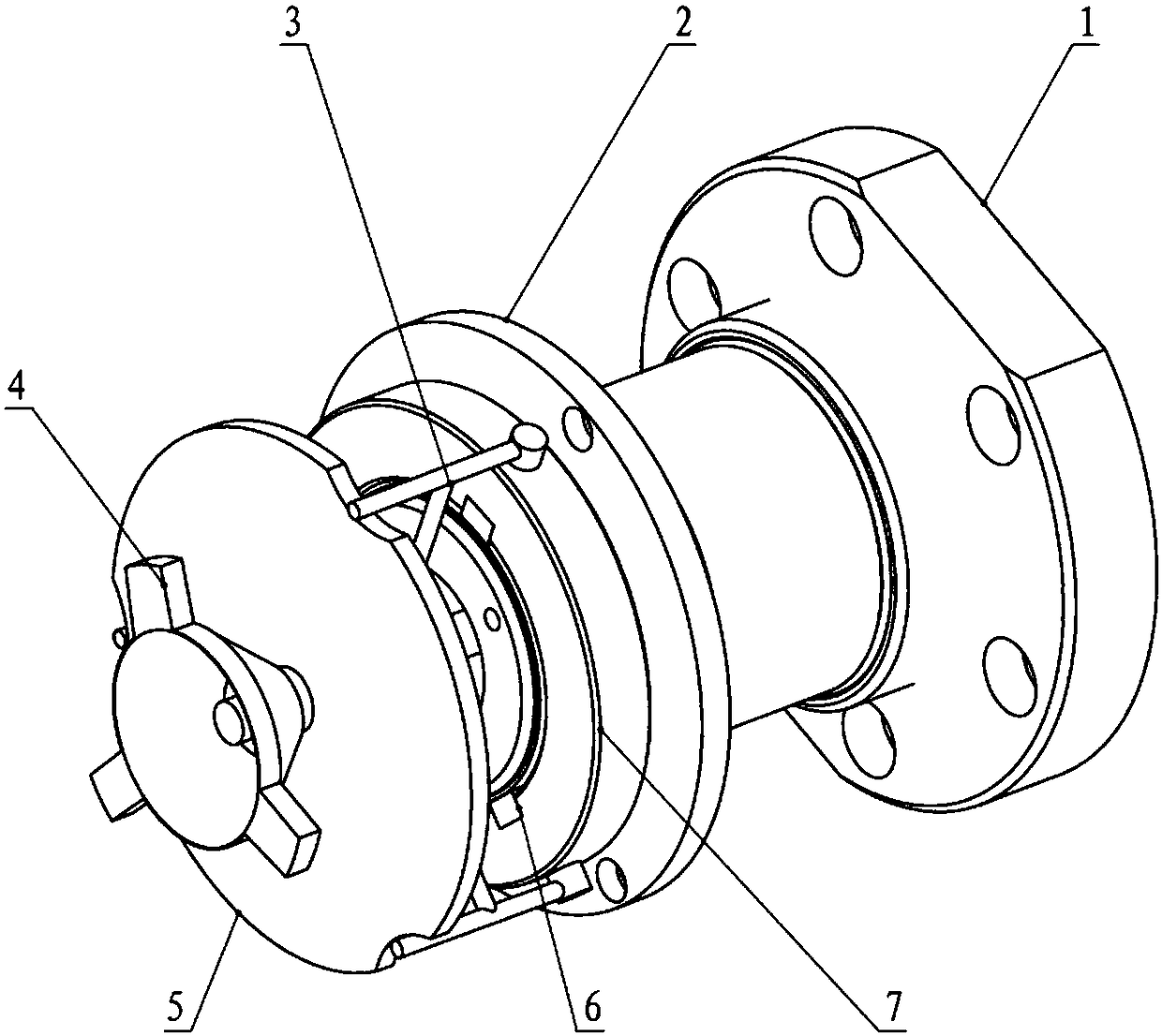
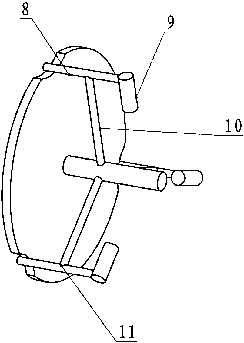
[0016] In the non-working state, shaft 1 stops rotating, and shaft 1 needs to be locked. Handwheel 4 and cam 5 are fixed together. Turn handwheel 4, cam 5 and handwheel 4 will rotate together. The lowest point of the cam moves upwards. Through the action of the lever twisting point 11, the cylindrical end 9 of the lever in the floating sleeve 7 will move downwards, transmitting the force to the pressure block 6, and then the pressure block 6 transmits the pressing force to the elastic thin film. The wall sleeve 2 and the elastic thin-wall sleeve 2 will finally compress the shaft 1 from three different directions to achieve the effect of locking the shaft 1.

Embodiment 2

[0018] Under normal working conditions, unlock the firmly locked shaft. Loosen the hand wheel and rotate the hand wheel 4 in the opposite direction. The hand wheel 4 and the cam 5 are fixed together, and the cam 5 will move in the opposite direction. At this time, the tension of the tensioned lever device 3 is released, and the lever assembly 3 will return to its balance In the state, the pressure received by the pressure block 6 disappears, the elastic thin-wall sleeve loosens the tightly held shaft, the shaft 1 is unlocked, and the shaft will work normally under the driving torque of the motor.


PUM


Abstract

The invention discloses a rotary shaft mechanical locking device based on the lever micro-motion principle. The rotary shaft mechanical locking device is mainly composed of three main parts, namely acam mechanism, a lever device and a locking assembly. The locking principle of the locking device is characterized in that the cam mechanism is driven by a hand wheel to move, and the lever micro-motion principle is utilized, so that the lever mechanism is enabled to slightly move up and down by means of hinge points; and the appearances of the two ends of the lever device are reasonably arrangedso that the lever device can tightly press pressing blocks in the locking device. According to the rotary shaft mechanical locking device based on the lever micro-motion principle, the factors of thedeformation of shafting and the reliability of the locking effect are considered, the three pressing blocks are evenly arranged on the locking assembly, pressing and loosening of the pressing blocks are controlled through the lever device and the hand wheel, the structure is reliable and reasonable, and the operation is convenient.

Description

Technical field [0001] The invention relates to a device with a rotating shaft, especially for some devices that need to be locked at any time when not working. Background technique [0002] Existing mechanical locking devices usually work on the principle of restricting relative movement between two components. For example, the use of thread locking has a wide range of applications, but it is not suitable to be used alone in an environment that requires rapid conversion; the eccentric locking mechanism can easily cause damage to plastic materials; for the four-bar mechanism locking, its structure It is more complicated. In actual use, there may not be such a large space to place it; the current use of a relatively wide range of three-point self-retracting thin-walled sleeve locking also has the disadvantages of uneven locking force and inconvenient adjustment of size. . [0003] However, in actual production, we often need to use a mechanical locking mechanism, which has to over...

Claims


Application Information

Patent Timeline
IPC IPC(8): F16D63/00F16D65/00F16D65/02
CPCF16D63/00F16D65/00F16D65/02
Inventor 喻杰勇陈庐彪陈世炉陈盼盼
Owner JIUJIANG PRECISION MEASURING TECH RES INST
Why Eureka
Try Eureka