Supercharge Your Innovation With Domain-Expert AI Agents!

A control method for compound braking transition process

A compound braking and transition process technology, applied in electric braking systems, electric vehicles, vehicle components, etc., can solve the problems of increased hydraulic braking force, heat generation, low motor power generation efficiency, etc., to improve braking impact, good control effect, the effect of improving braking consistency

Active Publication Date: 2021-06-04
TONGJI UNIV
View PDF8 Cites 0 Cited by
  • Summary
  • Abstract
  • Description
  • Claims
  • Application Information

AI Technical Summary

Problems solved by technology

[0006] 3) When the braking demand remains unchanged, as the vehicle speed continues to decrease, when the motor speed decreases to the critical speed, the motor generates low efficiency and heats up seriously. The braking demand remains unchanged, and the hydraulic braking force increases sharply
Did not pay too much attention to the state of the impact during the entire braking process, resulting in the inability to reflect the actual effect of many braking energy recovery strategies

Method used


Image

  • A control method for compound braking transition process
  • A control method for compound braking transition process
  • A control method for compound braking transition process

Examples


Embodiment

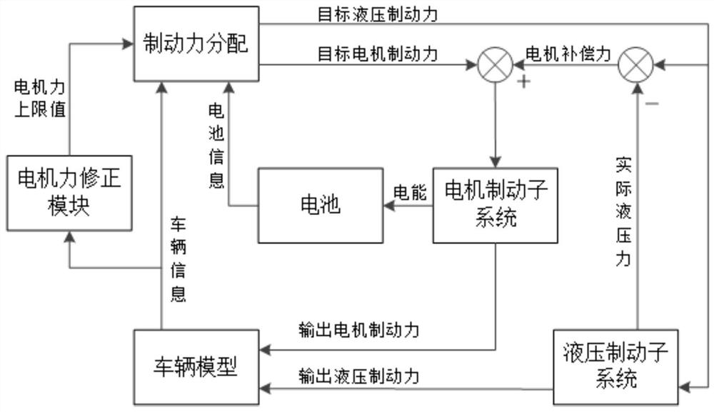
[0032] The invention relates to a method for controlling a composite braking transition process, which comprises the following steps:

[0033] Step 1. Based on the researched vehicle model and compound braking system, analyze vehicle parameters and motor parameters, and determine that the braking deceleration corresponding to the upper limit of motor force is 0.1g.

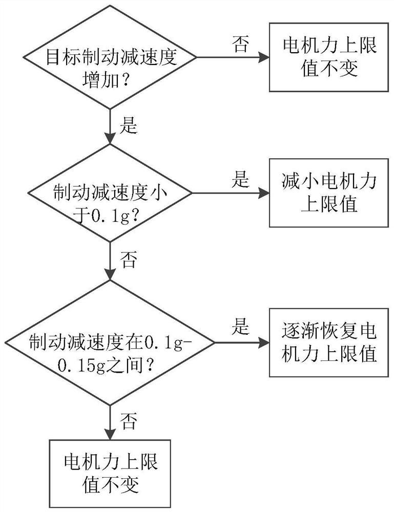
[0034] Step 2. Determine the logic algorithm of the motor force correction module based on the vehicle information and the data obtained in step 1:

[0035] Motor power correction logic such as figure 2 As shown, according to the state of the vehicle, if the braking demand is increasing and the braking deceleration is less than 0.1g, the hydraulic braking force is about to intervene at this time, so that the upper limit of the electric force of the braking force distribution is lower than the maximum value, so that the hydraulic braking Insufficient braking force due to lag during power intervention can be compe...


PUM


Abstract

The invention relates to a compound braking transition process control method. The method aims at the problem that there is a difference in the response speed between the motor brake subsystem and the hydraulic brake subsystem in the vehicle compound brake system. The motor braking force directly controls the hydraulic braking force. The deviation between the demand and the actual hydraulic braking force is compensated. In addition, a motor force correction module is added to enable the motor to have compensation capabilities under various transitional conditions. Compared with the prior art, the present invention improves the braking consistency of the motor in the hydraulic pressure intervention working condition, and can effectively reduce the impact of the composite braking transition process.

Description

technical field [0001] The invention relates to the technical field of composite braking of automobiles, in particular to a method for controlling the transition process of composite braking. Background technique [0002] The composite braking system generally includes a motor braking subsystem and a hydraulic braking subsystem. The braking demand of an electric vehicle is jointly responded by the regenerative braking of the driving motor and the hydraulic braking system. Electro-hydraulic brake system (Electro-hydraulic Brake System, EHB) is a new type of brake-by-wire system with active pressurization function, which is the development trend of automobile hydraulic brake system. It has precise control of hydraulic brake force and is easy to implement Outstanding advantages such as regenerative braking. [0003] When the vehicle is braking, the braking force distribution strategy uses the motor braking force first under the condition of ensuring the braking safety, and app...

Claims


Application Information

Patent Timeline
Patent Type & Authority Patents(China)
IPC IPC(8): B60L7/26
CPCB60L7/26
Inventor 熊璐史彪飞韩伟余卓平
Owner TONGJI UNIV
Features
  • R&D
  • Intellectual Property
  • Life Sciences
  • Materials
  • Tech Scout
  • Unparalleled Data Quality
  • Higher Quality Content
  • 60% Fewer Hallucinations
Learn More