Test tube clamping and positioning device and test tube cover opening and closing machine
A technology of clamping and positioning and positioning mechanism, applied in the field of medical devices, can solve the problems of biological injury, easy to splash out of operators, inconvenient operation, etc.
Pending Publication Date: 2019-03-01
SHANGHAI UPPER BIO TECH PHARMA
0 Cites 1 Cited by
AI-Extracted Technical Summary
Problems solved by technology
[0003] At present, the opening and closing of venous blood vessels is mostly done manually by operators, which is inconvenient to operate and low in work efficiency
At the same time, due ...
Method used
(4) in the test tube clamping and positioning device of the present invention, by making the clamping head made of rubber material, the surface friction between the clamping head and the test tube can be increased, and then the test tube can be firmly clamped, At the same time, damage to the surface of the test tube can be avoided.
In the present embodiment, as shown in Figure 3, the top of the first driving seat 41 is provided with the first positioning installation part 411 that cross section (section on the clamping direction) is L-shaped, and the second driving seat 42 is provided with an L-shaped second positioning installation portion 421 . The first fixing base 311 is installed on the first positioning installation part 411 , and the second fixing base 321 is installed on the second positioning installation part 421 . In this way, by providing the positioning installation part, the first clamping block assembly 31 and the second clamping block assembly 32 can be quickly and accurately installed on the corresponding driving seat.
[0056] In this embodiment, the first clamping block assembly 31 and the second clamping block assembly 32 are arranged facing each other in the clamping direction. In this way, it is beneficial to safely and stably clamp the test tube 5 .
[0062] In this embodiment, the first clamping head 315 is made of rubber material. In this way, t...
Abstract
The invention relates to a test tube clamping and positioning device and a test tube cover opening and closing machine. The test tube clamping and positioning device comprises a positioning mechanism,a clamping mechanism and a driving mechanism, the positioning mechanism comprises a positioning baffle for positioning a test tube rack for mounting test tubes, the clamping mechanism comprises a first clamping block assembly and a second clamping block assembly, the first clamping block assembly and the second clamping block assembly are located on the two sides of a positioning position formedby the positioning mechanism in the clamping direction, and the driving mechanism is used for driving the first clamping block assembly and the second clamping block assembly to move in opposite directions in the clamping direction to clamp the test tubes. The test tube clamping and positioning device can accurately and stably clamp and position the test tubes by the mutual cooperation of the positioning mechanism, the clamping mechanism and the driving mechanism.
Application Domain
Opening closed containersCaps +2
Technology Topic
Testing tubesEngineering
Image
Examples
- Experimental program(1)
Example Embodiment
[0040] The exemplary embodiments of the present invention are described below with reference to the drawings. It should be understood that these specific descriptions are only used to teach those skilled in the art how to implement the present invention, and are not used to exhaust all possible ways of the present invention, nor to limit the protection scope of the present invention.
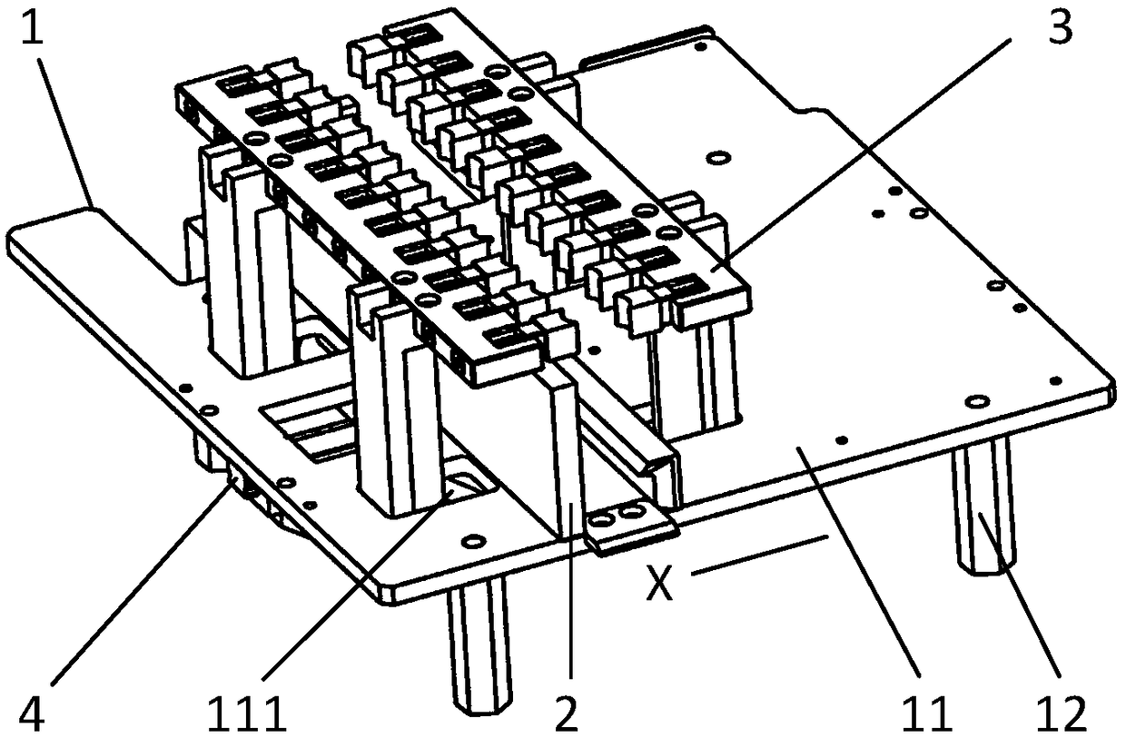
[0041] The "clamping direction" mentioned in the present invention refers to the moving direction of the first clamping block assembly and the second clamping block assembly during the clamping movement, that is, figure 1 In the X direction.
[0042] The “synchronization of the strokes of the first clamping block assembly and the second clamping block assembly" mentioned in the present invention means that the first clamping block assembly and the second clamping block assembly do not touch the test tube before the first clamping block assembly The traveling speed of the block assembly and the second clamping block assembly under the driving of the driving mechanism are equal.
[0043] Combine below Figure 1 to Figure 5 The specific implementation of the test tube clamping and positioning device according to the present invention will be described in detail.
[0044] In this embodiment, as figure 1 with Figure 5 As shown, the test tube clamping and positioning device according to the present invention includes an installation reference mechanism 1, a positioning mechanism 2, a clamping mechanism 3 and a driving mechanism 4.
[0045] Among them, the installation reference mechanism 1 is equipped with a positioning mechanism 2, a clamping mechanism 3 and a driving mechanism 4. The positioning mechanism 2 is used to position the test tube rack 6 for installing the test tube 5, and the driving mechanism 4 can drive the clamping mechanism 3 to clamp the test tube. 5.
[0046] In this embodiment, as figure 1 As shown, the mounting reference mechanism 1 includes a mounting reference plate 11 and a supporting leg 12. Wherein, the overall shape of the installation reference plate 11 is substantially rectangular, and the supporting legs 12 are installed below the installation reference plate 11.
[0047] In this embodiment, as figure 1 , image 3 with Figure 5 As shown, the mounting reference plate 11 has a limit slot 111 for limiting the stroke of the clamping mechanism 3.
[0048] In this embodiment, there are four supporting legs 12.
[0049] In this embodiment, as figure 1 with figure 2 As shown, the positioning mechanism 2 includes a first positioning baffle 21, a second positioning baffle 22 and a foolproof block 23.
[0050] In this embodiment, as figure 1 with figure 2 As shown, the first positioning baffle 21 has a rectangular shape as a whole, and is fixedly installed on the upper surface of the mounting reference plate 11 and extends perpendicular to the clamping direction.
[0051] In this embodiment, the second positioning baffle 22 has a rectangular shape as a whole, and is fixedly installed on one side of the mounting reference plate 11 and extends along the clamping direction.
[0052] In this embodiment, the first positioning baffle 21 and the second positioning baffle 22 form a positioning position for positioning the test tube rack 6.
[0053] In this embodiment, as figure 1 with figure 2 As shown, the foolproof stopper 23 is arranged on one side of the first positioning baffle 21 in the clamping direction, and is fixedly installed on the upper surface of the mounting reference plate 11 and extends perpendicular to the clamping direction.
[0054] In this embodiment, as image 3 with Figure 5 As shown, the fool-proof block 23 is formed with a fool-proof recess 231, and the fool-proof recess 231 is used to cooperate with the fool-proof convex part 61 (fool-proof part) formed on the test tube rack 6. In this way, it can be ensured that the test tube rack 6 is correctly placed in the positioning position.
[0055] In this embodiment, as figure 1 with figure 2 As shown, the clamping mechanism 3 includes a first clamping block assembly 31 and a second clamping block assembly 32. Among them, the first clamping block assembly 31 and the second clamping block assembly 32 are located on both sides of the positioning position formed by the positioning mechanism 2 in the clamping direction, and the first clamping block assembly 31 and the second clamping block assembly 32 It can move toward and away from each other in the clamping direction under the driving of the driving mechanism 4.
[0056] In this embodiment, the first clamping block assembly 31 and the second clamping block assembly 32 are arranged directly opposite in the clamping direction. In this way, it is beneficial to hold the test tube 5 safely and stably.
[0057] In this embodiment, as figure 1 with Figure 4 As shown, the first clamping block assembly 31 includes a first fixing seat 311, a first guiding and fixing shaft 312, and a first clamping head assembly. Wherein, the first fixing seat 311 is provided with a first guide groove 3111 and a first guide hole 3112 extending along the clamping direction.
[0058] In this embodiment, as Figure 4 As shown, the first guiding and fixing shaft 312 includes a first limiting boss 3121 and a first insertion shaft 3122. The first insertion shaft 3122 extends from one end surface of the first limiting boss 3121 in the clamping direction. Wherein, one end of the first limiting boss 3121 where the first insertion shaft 3122 abuts against an end surface of the first guide hole 3112, and the first insertion shaft 3122 passes through the first guide hole 3112 and extends into the first guide groove 3111.
[0059] In this embodiment, as Figure 4 As shown, the first clamping head assembly includes a first spring 313 (elastic telescopic mechanism), a first connecting block 314 and a first clamping head 315. Wherein, the first connecting block 314 is fixedly connected with one end of the first insertion shaft 3122 located in the first guide groove 3111, the first spring 313 is sleeved on the first guide fixing shaft 312, and both ends of the first spring 313 are respectively pressed against Connecting the first fixing seat 311 and the first connecting block 314, the first clamping head 315 is installed on the side of the first connecting block 314 opposite to the first spring 313.
[0060] In this embodiment, when the first clamping head 315 contacts the test tube 5 and clamps the test tube 5, the first clamping head 315 (with the first mounting block 314 and the first guide fixing shaft 312) is in the test tube 5 Under the force of, the first spring 313 is compressed and moved toward the first fixing seat 311, thereby achieving elastic clamping of the test tube 5, which can automatically adapt to test tubes of different diameters.
[0061] In this embodiment, the first connecting block 314 is at least partially located in the first guide groove 3111. In this way, it can be ensured that the first connecting block 314 and the first clamping head 315 move stably along the clamping direction.
[0062] In this embodiment, the first clamping head 315 is made of rubber material. In this way, the surface friction between the clamping head and the test tube 5 can be increased, so that the clamping is more stable and reliable. At the same time, damage to the surface of the test tube 5 can be avoided.
[0063] In this embodiment, as figure 2 As shown, the first clamping head 315 has a first arc-shaped groove 3151 that matches the tube wall of the test tube 5. In this way, the contact area between the clamping head and the test tube 5 can be further increased, the clamping force is increased, and the clamping is more stable.
[0064] In this embodiment, ten first clamping head assemblies are provided on the first fixing seat 311, which can clamp ten test tubes 5 at the same time.
[0065] In this embodiment, the second clamping block assembly 32 includes a second fixing seat 321, a second guiding and fixing shaft 322, and a second clamping head assembly. Wherein, the second guiding and fixing shaft 322 includes a second limiting boss and a second insertion shaft, and the second clamping head assembly includes a second spring 323 (elastic telescopic mechanism), a second connecting block 324 and a second clamping head 325 , The second fixing seat 321 is provided with a second guide groove 3211 and a second guide hole, and the second clamping head 325 has a second arc-shaped groove 3251.
[0066] In this embodiment, the structure of the components of the second clamping block assembly 32 and the connection between them are the same as the structure of the components of the first clamping block assembly 31 and the connections between them. I won't repeat them here.
[0067] Taking into account the manufacturing and installation errors of springs, clamping heads, etc., there is a gap between the test tube 5 and the wall surface of the chamber of the test tube rack 6 for accommodating the test tube 5. When the first clamping block assembly 31 and the second clamping block assembly 32 When simultaneously contacting the test tube 5 for clamping, the force on the test tube 5 may be uneven, and the test tube 5 may be clamped.
[0068] Therefore, in this embodiment, in the process of clamping the test tube 5, the second clamping block assembly 32 can first contact the test tube 5 for pre-position clamping compared to the first clamping block assembly 31. That is, the second clamping block assembly 32 can press the test tube 5 against the inner wall of the test tube rack 6 for accommodating the test tube 5 in advance. At the same time, the test tube rack 6 will abut the first positioning baffle 21, and then the first The clamping block assembly 31 then contacts the test tube 5 to clamp the test tube 5. In this way, the test tube 5 can be prevented from being clamped.
[0069] In this embodiment, as Figure 5 As shown, under the drive of the driving mechanism 4, the strokes of the first clamping block assembly 31 and the second clamping block assembly 32 are synchronized, and when the test tube rack 6 is installed in the positioning position, the clamping of the second clamping block assembly 32 The distance between the holding end and the center line of the test tube 5 perpendicular to the clamping direction is smaller than the distance between the holding end of the first clamping block assembly 31 and the center line of the test tube 5 perpendicular to the clamping direction, so that the second clamping block The assembly 32 can contact the test tube 5 first. Of course, the present invention is not limited to this.
[0070] In this embodiment, as figure 1 with image 3 As shown, the driving mechanism 4 includes a first driving seat 41, a second driving seat 42 and a driving source. Wherein, the first driving seat 41 and the second driving seat 42 are both connected with a driving source, and the first driving seat 41 and the second driving seat 42 can be driven by the driving source to move toward and away from each other in the clamping direction.
[0071] In this embodiment, the drive source is installed below the mounting reference plate 11. Among them, the drive source can use components such as motors, drive cylinders, etc. as power sources, and use worm gears, screw nuts, gears, etc. as transmission components. The present invention does not limit this.
[0072] In this embodiment, as image 3 As shown, the upper part of the first driving seat 41 is provided with a first positioning mounting portion 411 having an L-shaped cross section (a cross-section in the clamping direction), and the upper part of the second driving seat 42 is provided with a second positioning part 411 having an L shape. Installation part 421. The first fixing seat 311 is installed on the first positioning installation portion 411, and the second fixing seat 321 is installed on the second positioning installation portion 421. In this way, by providing the positioning and mounting parts, the first clamping block assembly 31 and the second clamping block assembly 32 can be quickly and accurately installed on the corresponding driving seat.
[0073] In this embodiment, as figure 1 with image 3 As shown, the first driving seat 41 and the second driving seat 42 are both inserted into the corresponding limiting groove 111. In this way, when the driving mechanism 4 fails, the limit slot 111 can mechanically limit the driving seat to prevent the clamping mechanism from clamping the test tube.
[0074] The working process of the test tube clamping and positioning device according to the present invention will be briefly described below.
[0075] When the test tube 5 needs to be clamped and positioned, the test tube rack 6 equipped with the test tube 5 is placed at the positioning position formed by the positioning mechanism 2. Next, the driving mechanism 4 acts to drive the first clamping block assembly 31 and the second clamping block assembly 32 to move toward each other synchronously.
[0076] The second clamping block assembly 32 will first contact the test tube 5 and press the test tube 5 against the inner wall of the test tube rack 6 for accommodating the test tube 5. At the same time, the test tube rack 6 will press against the first positioning baffle 21. Then, the first clamping block assembly 31 moves to contact the test tube 5 and clamp the test tube 5.
[0077] So far, the clamping and positioning of the test tube 5 is completed.
[0078] By adopting the above technical solution, the test tube clamping and positioning device according to the present invention has the following advantages:
[0079] (1) In the test tube clamping and positioning device of the present invention, the test tube can be clamped and positioned accurately and stably through the mutual cooperation of the positioning mechanism, the clamping mechanism and the driving mechanism.
[0080] (2) In the test tube clamping and positioning device of the present invention, by making the second clamping block assembly contact the test tube first to clamp the test tube in a pre-position, it is possible to avoid clamping the test tube.
[0081] (3) In the test tube clamping positioning device of the present invention, a spring is provided in the clamping head assembly, so that the clamping head assembly can adapt to test tubes of different diameters.
[0082] (4) In the test tube clamping and positioning device of the present invention, by making the clamping head made of rubber material, the surface friction between the clamping head and the test tube can be increased, and the test tube can be clamped firmly. Avoid damaging the surface of the test tube.
[0083] (5) In the test tube clamping and positioning device of the present invention, the clamping head assembly can be quickly and accurately installed by arranging the positioning installation part on the driving seat.
[0084] (6) In the test tube clamping and positioning device of the present invention, by providing a limit slot on the mounting reference plate, the test tube can be prevented from being clamped when the driving mechanism fails.
[0085] (7) In the test tube clamping and positioning device of the present invention, the foolproof stopper is provided, so that the test tube rack can be quickly and accurately placed at the positioning position.
[0086] The above specific implementations have described the technical solutions of the present invention in detail, but what needs to be supplemented is:
[0087] (1) Although in the above embodiment it is described that the fool-proof block is formed with a fool-proof concave portion to cooperate with the fool-proof convex portion formed on the test tube rack, the present invention is not limited to this, and the fool-proof block may also be formed with Foolproof convex part, correspondingly, a foolproof concave part is formed on the test tube rack to cooperate with the foolproof convex part.
[0088] (2) Although it is described in the above embodiment that the first clamping block assembly and the second clamping block assembly are arranged opposite to each other in the clamping direction, the present invention is not limited to this, the first clamping block assembly and the second clamping block The tight block components can also be staggered in the up and down direction.
[0089] (3) Although it is described in the above embodiment that the second clamping block assembly first contacts the test tube, the present invention is not limited to this. Depending on the position and structure of the first positioning baffle, the first clamping block assembly may also first contact the test tube. test tube.
[0090] (4) Although the strokes of the first clamping block assembly and the second clamping block assembly are synchronized in the above embodiments, the clamping end of the second clamping block assembly is far from the center line of the test tube perpendicular to the clamping direction. The distance is closer, but the present invention is not limited to this. The strokes of the first clamping block assembly and the second clamping block assembly may not be synchronized. The respective clamping ends of the first clamping block assembly and the second clamping block assembly and the test tube The distance from the center line perpendicular to the clamping direction can also be equal. Correspondingly, the travel speed of the first clamping block assembly and the second clamping block assembly can be controlled to make the second clamping block assembly contact the test tube first.
[0091] (5) Although it is described in the above embodiment that the positioning and mounting portion is L-shaped, the present invention is not limited to this. The positioning and mounting portion may be configured as an arc-shaped groove, a rectangular groove, or other shapes, or may be configured as a protrusion shape.
[0092] In addition, the present invention also provides a test tube opening and closing machine. The test tube opening and closing machine includes a test tube opening and closing device and the above-mentioned test tube clamping and positioning device. The test tube opening and closing device is used for opening and closing the test tube after the test tube is clamped by the test tube clamping positioning device.
[0093] It can be understood that when the test tube clamping and positioning device clamps the test tube, it clamps the tube body under the test tube cover of the test tube.
[0094] Similarly, the test tube opening and closing machine with the test tube clamping and positioning device also has the same advantages.
PUM


Description & Claims & Application Information
We can also present the details of the Description, Claims and Application information to help users get a comprehensive understanding of the technical details of the patent, such as background art, summary of invention, brief description of drawings, description of embodiments, and other original content. On the other hand, users can also determine the specific scope of protection of the technology through the list of claims; as well as understand the changes in the life cycle of the technology with the presentation of the patent timeline. Login to view more.