
Determination of a gas concentration

A technology of gas concentration and concentration, which is applied to the structural details of gas analyzers, the analysis of gas mixtures, sensors, etc., which can solve the problems of inaccurate measurement and unusability

Inactive Publication Date: 2019-03-01
ROBERT BOSCH GMBH
View PDF7 Cites 0 Cited by
  • Summary
  • Abstract
  • Description
  • Claims
  • Application Information

AI Technical Summary

Problems solved by technology

If a predetermined inflow of the gas sensor by the medium to be measured does not take place during this measurement period, the measurement may be inaccurate or unusable.

Method used


Image

  • Determination of a gas concentration
  • Determination of a gas concentration
  • Determination of a gas concentration

Examples


Embodiment Construction

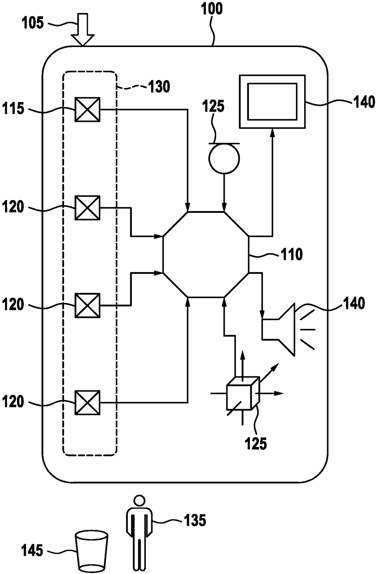
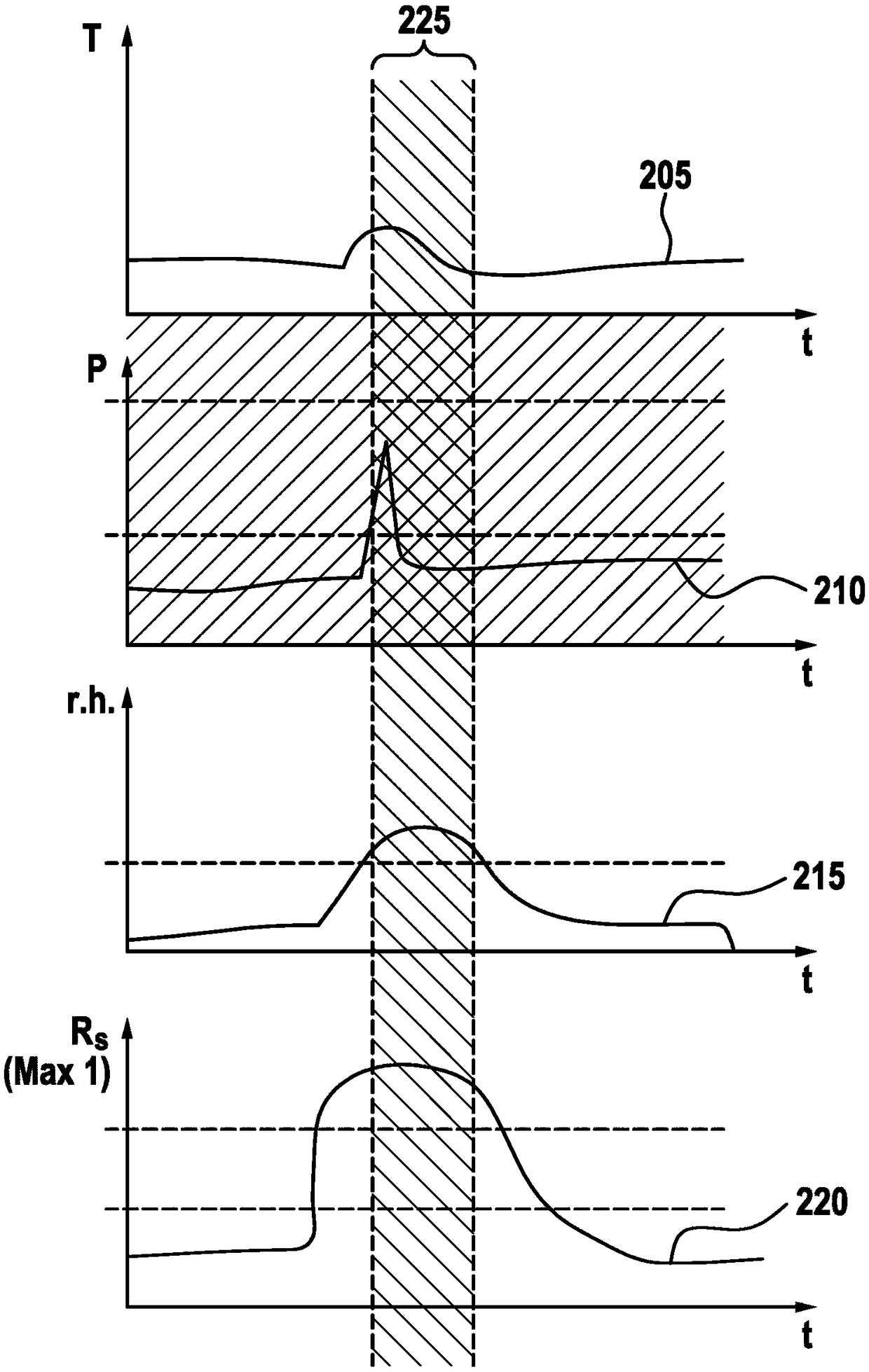
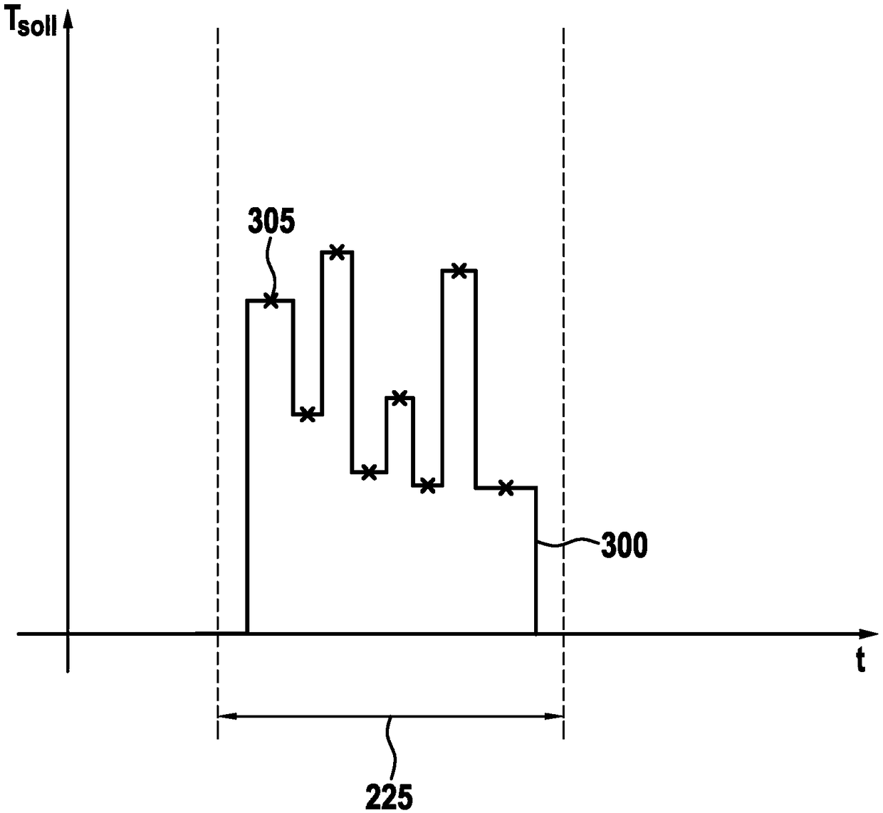
[0028] figure 1 A device 100 for determining the gas concentration in a medium 105 is shown. Device 100 may in particular be a component of a mobile device, such as a smartphone. The device 100 comprises a processing device 110, a first sensor 115 arranged to determine the concentration of a gas in the medium 105, one or more second sensors 120 arranged to determine different physical parameters of the medium 105 and preferably one or A plurality of third sensors 125 are arranged for sensing a physical parameter in the surroundings of the device 100 or in the surroundings of the first sensor 115, respectively. The third sensor 125 may include, for example, an acceleration sensor, a rotational speed sensor, a magnetic field sensor or a position sensor. In the preferred embodiment shown, the first sensor 115 and up to three second sensors 120 are integrated in a common sensor module 130 . In this example, the second sensor 120 is related to the temperature, pressure and relat...


PUM


Abstract

The invention relates to a device for determining the concentration of a predefined gas in a medium, which device comprises a first sensor for determining the gas concentration in a flow of the medium; a second sensor for determining a physical parameter of the medium in the flow of the medium; and a processing apparatus, which is designed to determine the quality of the determination by means ofthe first sensor on the basis of a signal of the second sensor.

Description

technical field [0001] The present invention relates to the determination of gas concentrations. The invention relates in particular to the determination of gas concentrations by means of free-jet flow measuring devices. Background technique [0002] The mobile appliance includes sensors for determining gas concentrations. The mobile device can be configured, for example, to determine the concentration of gaseous alcohol in the breathing air. Expensive analyzers usually include mechanical devices, such as nozzles or pumps, by means of which a predetermined inflow of breathing air is brought about to the gas sensor. Cheaper analyzers often work according to the free-jet measurement principle, in which a predetermined inflow to the gas sensor cannot be forced. In order to determine the gas concentration, the gas sensor usually has to be brought into a defined operating state or a series of predetermined operating states during a measuring process requiring a predetermined m...

Claims


Application Information

Patent Timeline
Patent Type & Authority Applications(China)
IPC IPC(8): G01N33/00A61B5/08G01N33/497
CPCA61B5/082G01N33/007G01N33/4972G01N33/0031A61B10/00A61B2010/0009A61B2010/0083A61B2010/0087
Inventor P·诺尔特R·菲克斯C·冯尤切恩卡切比亚托夫斯基
Owner ROBERT BOSCH GMBH
Learn More