
Riveting part

A technology of rivets and guide posts, applied in rivets and other directions, can solve the problem that it is difficult to effectively meet the pressure riveting requirements of ultra-thin plates, and achieve the effect of meeting the pressure riveting requirements.

Pending Publication Date: 2019-03-05
PEM CHINA
View PDF0 Cites 0 Cited by
  • Summary
  • Abstract
  • Description
  • Claims
  • Application Information

AI Technical Summary

Problems solved by technology

However, due to the limitations of its own structure and manufacturing process, traditional pressure riveting fasteners or fasteners are difficult to effectively meet the demand for pressure riveting of ultra-thin sheets

Method used


Image

  • Riveting part
  • Riveting part
  • Riveting part

Examples


Embodiment Construction

[0023] In the following detailed description, reference is made to the accompanying drawings which form a part hereof. The illustrative embodiments described in the detailed description, drawings, and claims are not intended to be limiting. Other embodiments may be utilized, and other changes may be made, without departing from the spirit or scope of the subject matter of the present application. It is to be understood that various configurations, substitutions, combinations, designs of various configurations, substitutions, combinations, and designs of the content of the application generally described in this application and illustrated in the accompanying drawings are possible, all of which expressly constitute the content of the application. part.

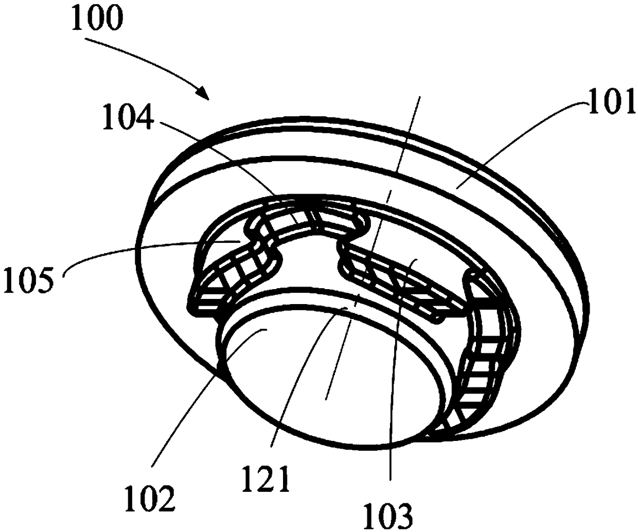
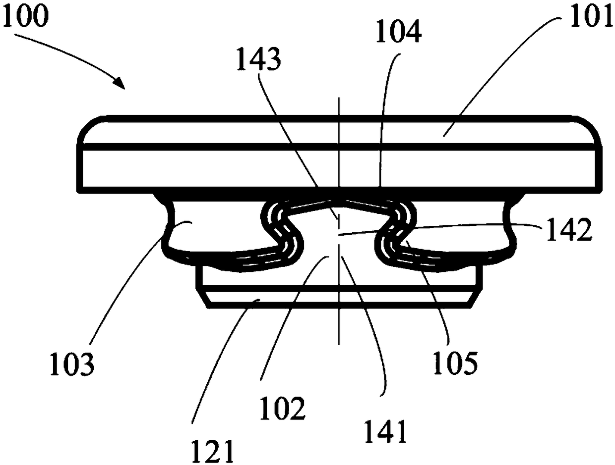
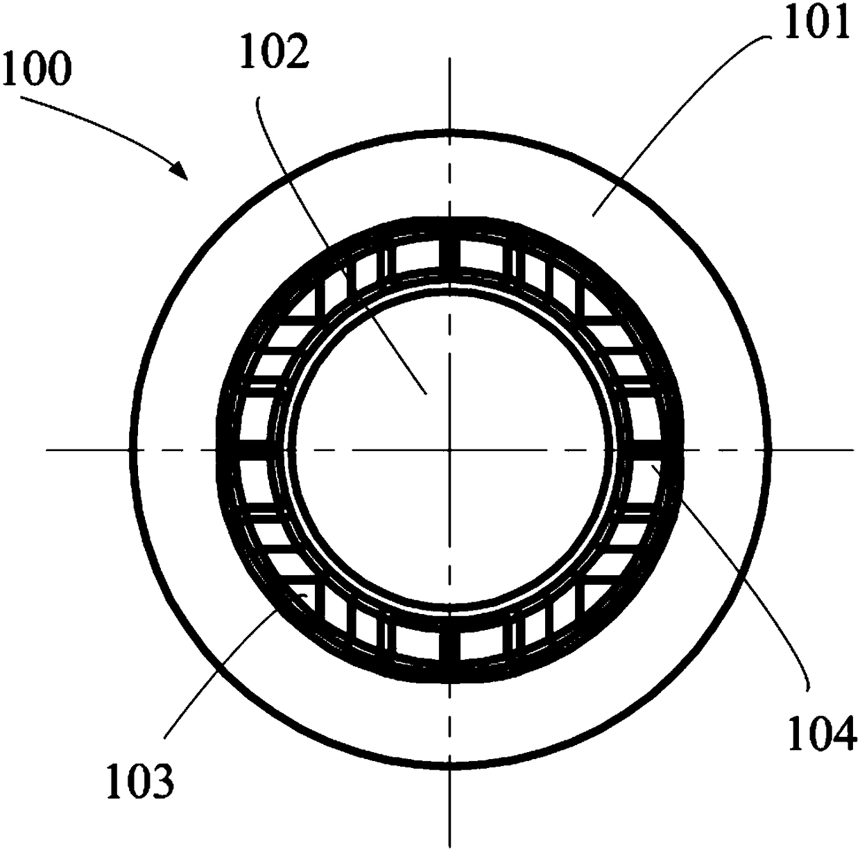
[0024] figure 1 A schematic diagram of a rivet 100 according to an embodiment of the present application is shown, figure 2 show figure 1 The front view of the shown rivet 100, image 3 show figure 1 A bottom view of the...


PUM


Abstract

The invention relates to a riveting part. The riveting part comprises a head portion, a guiding pillar and one or more locking portions, wherein the guiding pillar extends out of the head portion; thecross section of the guiding pillar is matched with a mounting hole in a to-be-riveted plate, so that the guiding pillar can be inserted into the mounting hole and move in the axial direction of theguiding pillar; and the locking portions extend out of the head portion and partly or wholly surround the guiding pillar. Each locking portion comprises one or more self-buckling grooves and discharging portions. The self-buckling grooves extend around the guiding pillar in the circumferential direction and used for containing materials, squeezed to flow, of the to-be-riveted plate when the to-be-riveted plate is riveted through the riveting part. The discharging portions are located at the two sides of the self-buckling grooves and used for squeezing the materials of the to-be-riveted plate,and thus, the materials flow into and are maintained in the self-buckling grooves.

Description

technical field [0001] The present application relates to riveting technology, and more specifically, to a riveting part. Background technique [0002] Pressure riveting is a riveting method that uses the static pressure generated by the riveting machine to upset the rivet rod to form an upset head. The riveted parts of pressure riveting have the characteristics of good surface quality, small deformation and high connection strength, so they are widely used in various mechanical processing fields, such as shipbuilding, automobile manufacturing, aerospace, white goods, etc. In recent years, with the rapid development of the household consumer electronics market, the demand for pressure riveting of ultra-thin sheets in electronic products is also increasing. However, due to the limitations of its own structure and manufacturing process, traditional pressure riveting fasteners or fasteners are difficult to effectively meet the demand for pressure riveting of ultra-thin sheets....

Claims


Application Information

Patent Timeline
IPC IPC(8): F16B19/06
CPCF16B19/06Y02E60/10
Inventor 陈小明Q·孙
Owner PEM CHINA
Learn More