A kind of elliptical rolling piston and rolling piston compressor

A rolling piston, elliptical technology, applied in the field of compressors, can solve the problems of large compressors that cannot be rolled piston compressors, increase the movement speed and clearance, and reduce machine performance, so as to eliminate the eccentric mass and centrifugal force, and increase the actual Contact area, effect of increasing curvature

Active Publication Date: 2020-08-18
重庆竟由科技发展有限公司
View PDF6 Cites 0 Cited by
  • Summary
  • Abstract
  • Description
  • Claims
  • Application Information

AI Technical Summary

Problems solved by technology

However, the circular rolling piston between the sliding vane and the rotor of the traditional rolling piston compressor causes the relative movement speed and gap between the sliding vane to increase, which will cause large leakage and friction problems, which will greatly reduce the performance of the machine.
And the traditional rolling piston compressor cannot be made into a large compressor due to the balance quality problem

Method used


Image

  • A kind of elliptical rolling piston and rolling piston compressor
  • A kind of elliptical rolling piston and rolling piston compressor
  • A kind of elliptical rolling piston and rolling piston compressor

Examples


Embodiment Construction

[0026] The present invention will be further described in detail below in conjunction with the drawings.

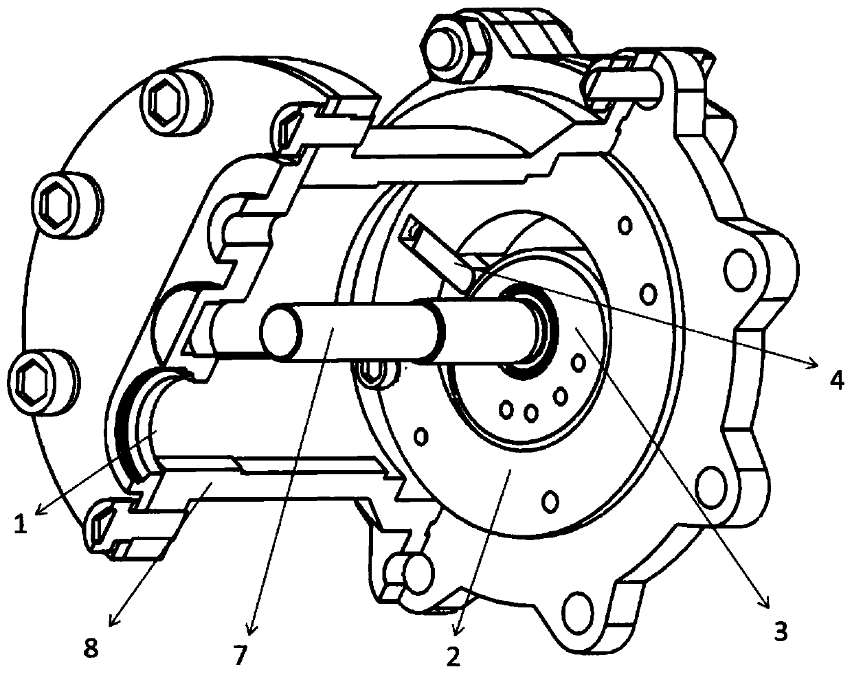
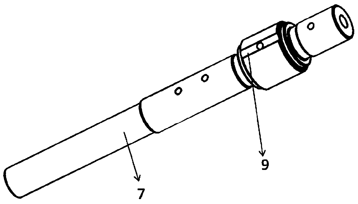
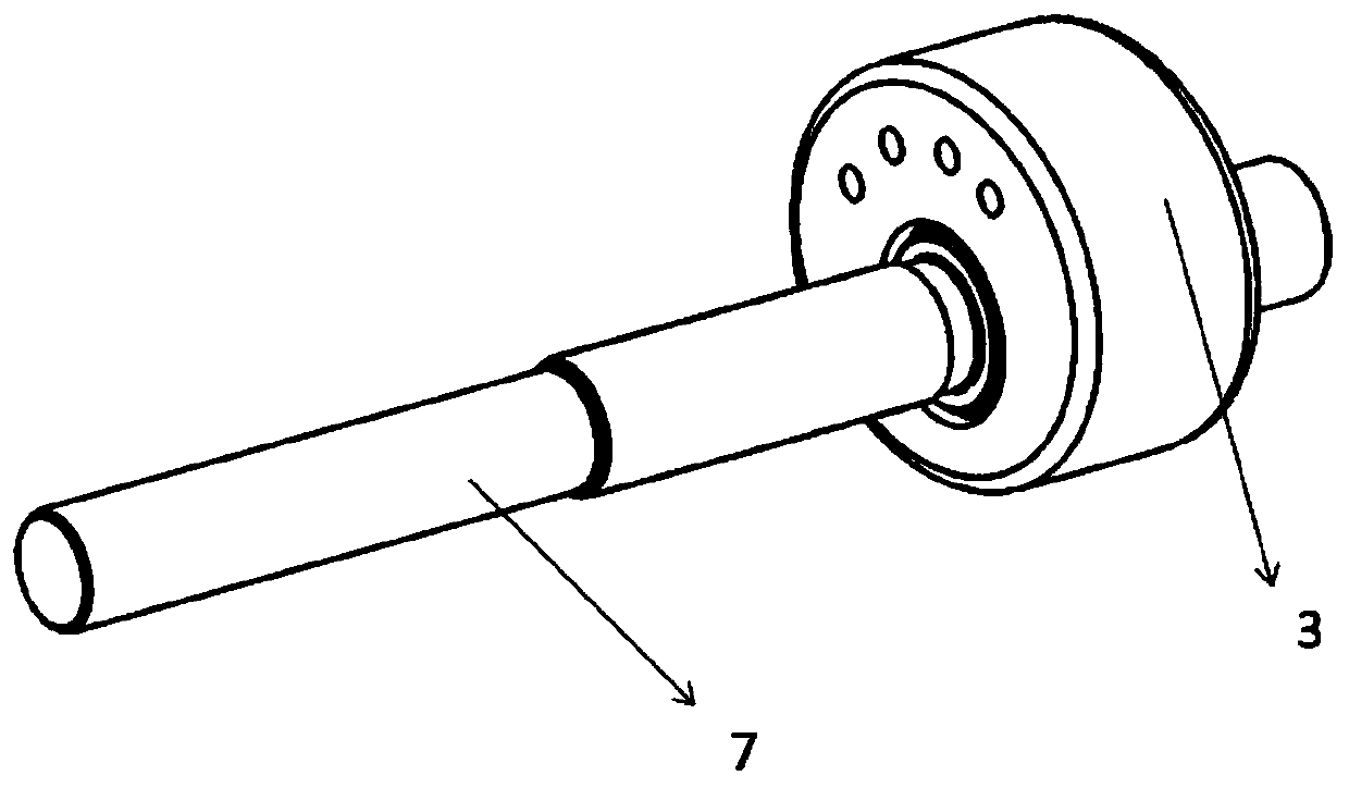
[0027] The rolling piston compressor adopting the oval-shaped rolling piston of the present invention includes a cylinder 2, a sliding vane 4, a piston 3, an intake hole 1, an exhaust hole 5, an exhaust valve, and a sliding vane spring 6. The cylinder 2 Fixed on the casing 8, the piston 3 and the main shaft 7 are connected by a key, and the rotation of the main shaft 7 drives the rolling piston 3 to rotate. The spring force of the sliding leaf spring 6 makes the sliding leaf 4 and the piston 3 closely contact, the sliding leaf 4 can move up and down, and is always in contact with the piston 3. The working process of the compressor of the present invention is as follows: when the tangent point T between the piston 3 and the cylinder 2 reaches the point A of the intake port 1, the element area communicates with the intake port 1. As the piston 3 rotates, the element The area ...


PUM


Abstract

The invention relates to a quasi-elliptic rolling piston and a rolling piston compressor. The quasi-elliptic rolling piston has a profile formed by combining a plurality of molded lines; the center ofmass coincides with a main shaft; a piston body is concentric with a cylinder; compared with a circular rolling piston, the quasi-elliptic rolling piston has a greater radius of curvature at a contact point with the cylinder, the up-and-down motion rate of a sliding sheet can be reduced in the exhaust process, and the friction angles between the quasi-elliptic rolling piston and the cylinder andbetween the quasi-elliptic rolling piston and the sliding sheet can be reduced; and the radiuses of curvature of the molded lines of various portions at the combined and connected parts are the same.The rolling piston compressor comprises the cylinder; the piston is arranged in a cavity of the cylinder; the piston is fixedly connected with the main shaft and driven to make rotary motion by the main shaft; the sliding sheet capable of being in close contact with the piston all the time is arranged on the inner wall of a cavity of the cylinder; the sliding vane is supported by a sliding sheet spring; an air inlet hole and an exhaust hole are formed in cylinder end covers at the two ends of a casing; and an exhaust valve is arranged on the exhaust hole. Friction and leakage of the piston canbe reduced, and the size and mass of the piston are increased.

Description

Technical field [0001] The invention relates to the field of compressors, in particular to an oval-shaped rolling piston and a rolling piston compressor. Background technique [0002] The rolling piston compressor is also called the rolling rotor compressor. Due to the rapid development of modern processing technology, the technology of rolling piston compressors has become increasingly perfect. Especially after the 1970s, rolling piston compressors accounted for an increasing proportion of small hermetic refrigeration compressors. As a positive displacement compressor, a rolling piston compressor uses a rotating rotor, a cylinder, and a sliding vane to form a periodically changing closed volume chamber to compress gas. Compared with the reciprocating compressor, the volume can be reduced by 40%-50%, the weight is 50% lighter, and the vulnerable parts can be reduced by 35%-40%, and it can be used to transport dirty, liquid droplet, and dust-containing process gas. Therefore, r...

Claims


Application Information

Patent Timeline
Patent Type & Authority Patents(China)
IPC IPC(8): F04C18/356F04C29/00
CPCF04C18/356F04C29/00F04C2240/20F04C2240/80
Inventor 何志龙曲西德李丹童韩耀祥吴伟烽邢子文
Owner 重庆竟由科技发展有限公司
Why Eureka
Try Eureka