System and method for controlling bidirectional direct current power supply of transformer substation

A technology of DC power supply and control system, applied in the field of substations, can solve the problems of time-consuming and complicated operation, and achieve the effect of reducing manual operation, simplifying system structure, and saving material and manpower

Active Publication Date: 2019-03-08
KEHUA DATA CO LTD +1
View PDF5 Cites 5 Cited by
  • Summary
  • Abstract
  • Description
  • Claims
  • Application Information

AI Technical Summary

Problems solved by technology

[0003] In view of this, the embodiment of the present invention provides a substation bidirectional DC power supply control system and method to solve the problem in the prior art that the DC power supply is only used for battery charging and load power supply, and when the battery pack is nuclear-capacitated in the substation. , a cumbersome and time-consuming problem

Method used


Image

  • System and method for controlling bidirectional direct current power supply of transformer substation
  • System and method for controlling bidirectional direct current power supply of transformer substation
  • System and method for controlling bidirectional direct current power supply of transformer substation

Examples


Embodiment 1

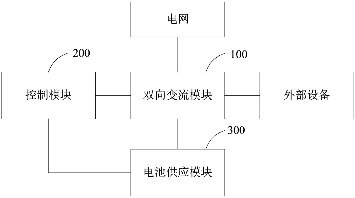
[0052] see figure 1 , a substation bidirectional DC power supply control system provided in this embodiment includes a bidirectional converter module 100 , a control module 200 and a battery power supply module 300 .

[0053]Wherein, the bidirectional converter module 100 is electrically connected to the battery power supply module 300 , and the control module 200 is respectively connected to the battery power supply module 300 and the bidirectional converter module 100 through a communication bus. In this embodiment, the structure of the communication bus is not limited, and it may be a CAN (Controller Area Network, controller area network) bus, or an RS485 bus.

[0054] Specifically, the bidirectional converter module 100 is used to send a grid disconnection signal to the control module 200 when the grid is powered off; the control module 200 is used to send an instruction to start an emergency power supply mode to the bidirectional converter module according to the grid dis...

specific Embodiment approach

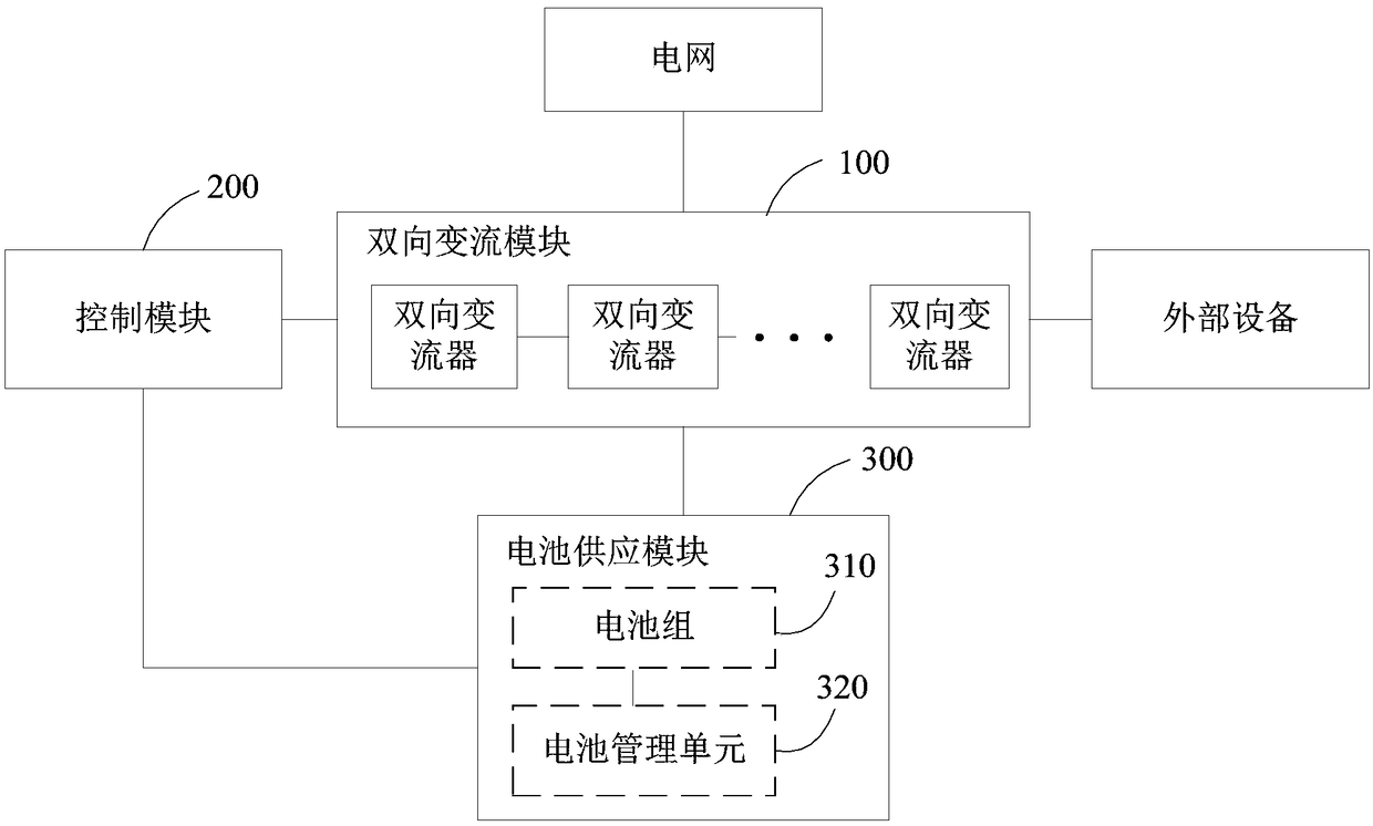
[0099] Further, see figure 2 , as another specific implementation manner, the battery power supply module 300 includes a battery pack 310 and a battery management unit 320 .

[0100] Wherein, the battery pack 310 is electrically connected to the bidirectional converter module 100 , the battery pack 310 is connected to the battery management unit 320 in communication, and the battery management unit 320 is connected to the control module 200 in communication. The battery management unit 320 can be connected to the control module 200 wirelessly, or can be connected to the control module 200 through a communication bus.

[0101] Specifically, the battery pack 310 is used to output the first direct current or the second direct current to the bidirectional converter module 100, that is, the battery pack 310 can receive the voltage of the power grid and store power, and can also be used as a power supply to provide power for external devices.

[0102] The battery management unit 3...

Embodiment 2

[0121] Corresponding to the substation bidirectional DC power control system in Embodiment 1, this embodiment provides a substation bidirectional DC power control method. For details, see Figure 5 , a schematic diagram of the implementation flow of an embodiment of the substation bidirectional DC power supply control method, as follows:

[0122]Step S501, when the grid is powered off, the bidirectional converter module sends a grid disconnection signal to the control module.

[0123] Step S502, the control module sends an instruction to start an emergency power supply mode to the bidirectional converter module according to the grid disconnection signal.

[0124] Step S503, the bidirectional converter module starts the emergency power supply mode according to the command to start the emergency power supply mode, and sends a first discharge command to the battery power supply module.

[0125] Step S504, the battery power supply module outputs a first direct current to the bid...


PUM


Abstract

The invention is applicable for the technical field of transformer substations, and provides a system and a method for controlling the bidirectional direct current power supply of a transformer substation. The system comprises a bidirectional conversion module, a control module and a battery power supply module, wherein the bidirectional conversion module is used for sending an off-grid signal tothe control module when a power grid is powered off; the control module is used for sending an emergency power supply mode starting command to the bidirectional conversion module according to the off-grid signal or sending a capacity check mode starting command to the bidirectional conversion module according to user input; the bidirectional conversion module is used for starting an emergency power supply mode and sending a first discharge command to the battery power supply module or sending a second discharge command to the battery power supply module in the capacity check mode; the batterypower supply module is used for outputting first direct current according to the first discharge command or outputting second direct current according to the second discharge command, and the bidirectional conversion module is used for recording the electric quantity information of second direct current. Power can be supplied emergently, the investment of uninterruptible power supply equipment isreduced, capacity check further can be carried out on the battery module automatically, manual operation is reduced, and the manpower and material resources are saved.

Description

technical field [0001] The invention belongs to the technical field of substations, and in particular relates to a substation bidirectional DC power supply control system and method. Background technique [0002] In the field of substations, the technology is single-phase DC power supply system. The DC power supply is only used as a battery charging and load power supply capacity, and its intelligent management ability is relatively backward, so that later operation and maintenance management also requires a large workload; Moreover, in the daily maintenance specification of the substation, at least once a year, the nuclear capacity of the battery pack is required. In the previous mode, maintenance personnel were required to move the battery discharge instrument to the corresponding substation, disconnect the battery pack and discharge the battery pack to the nuclear capacity separately. And it is necessary to do a good job in the corresponding battery core capacity data wor...

Claims


Application Information

Patent Timeline
Patent Type & Authority Applications(China)
IPC IPC(8): H02J3/02H02J9/06H02J7/00H01M10/42
CPCH01M10/42H02J3/02H02J7/0013H02J7/0068H02J9/06Y02E60/10
Inventor 冯晓滨姚美齐林金水
Owner KEHUA DATA CO LTD
Why Eureka
Try Eureka