Lifting fence for municipal engineering
A technology of fencing and engineering, applied in the field of fencing, can solve the problems of wasting manpower, material and financial resources, troubles, etc., and achieve the effect of saving manpower and financial resources
- Summary
- Abstract
- Description
- Claims
- Application Information
AI Technical Summary
Problems solved by technology
Method used
Image

Examples
Embodiment 1
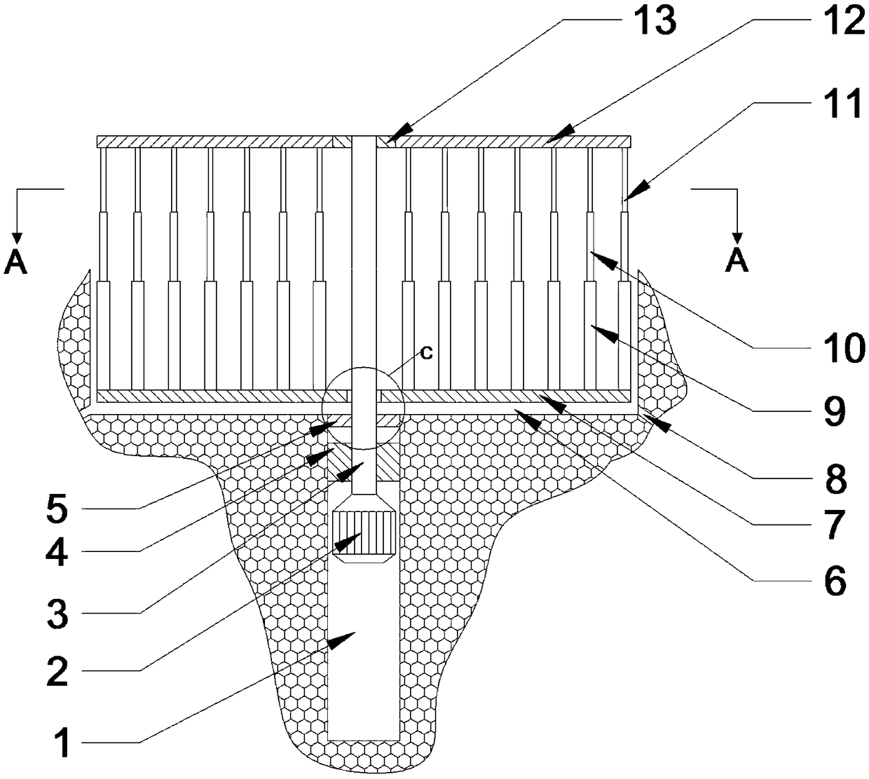
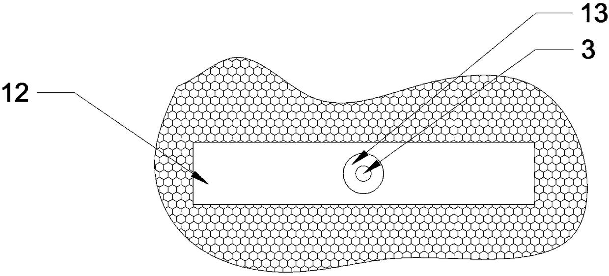
[0037] Such as Figure 1-9Shown, a kind of lifting fence that is used for municipal engineering, comprises the fence groove 6 that opens on the ground, and fence groove 6 li is equipped with lower fence board 7, and the top surface of lower fence board 7 is installed with a plurality of telescopic rods in vertical direction , the upper fence board 12 is installed on the top surface of a plurality of telescopic rods, and the bearing 13 is installed in the middle part of the upper fence board 12; An adjusting plate 4 is fixedly installed, and a motor 2 is arranged in the motor groove 1. The motor 2 is connected with a rotating shaft 3 passing through the adjusting plate 4 and the lower fence plate 7. The rotating shaft 3 and the adjusting plate 4 are connected by threads, and the upper end of the rotating shaft 3 is installed on a bearing 13 in.
[0038] In the present invention, when a fence is required at the place where the fence is installed, it is only necessary to turn on...
Embodiment 2
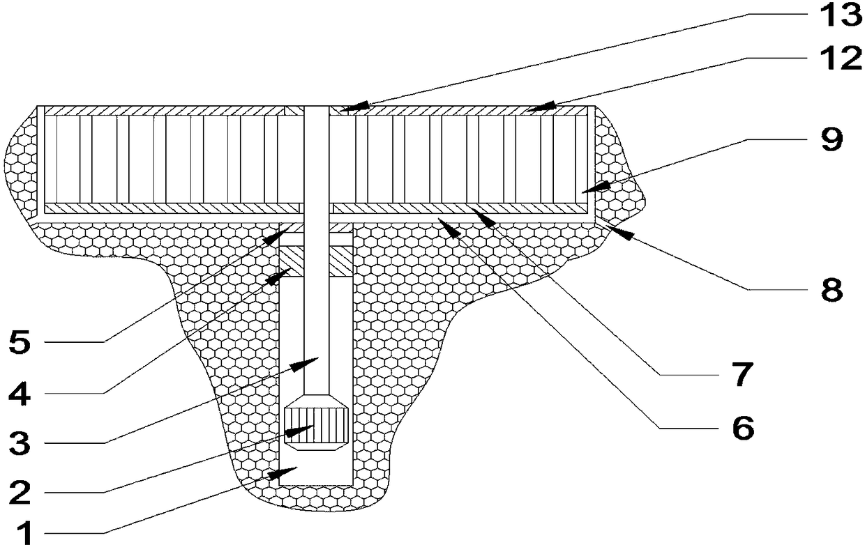
[0040] Such as Figure 1-9 Shown, a kind of lifting fence that is used for municipal engineering, comprises the fence groove 6 that opens on the ground, and fence groove 6 li is equipped with lower fence board 7, and the top surface of lower fence board 7 is installed with a plurality of telescopic rods in vertical direction , the upper fence board 12 is installed on the top surface of a plurality of telescopic rods, and the bearing 13 is installed in the middle part of the upper fence board 12; An adjusting plate 4 is fixedly installed, and a motor 2 is arranged in the motor groove 1. The motor 2 is connected with a rotating shaft 3 passing through the adjusting plate 4 and the lower fence plate 7. The rotating shaft 3 and the adjusting plate 4 are connected by threads, and the upper end of the rotating shaft 3 is installed on a bearing 13 in.
[0041] In this embodiment, the first telescopic rod 9, the second telescopic rod 10 and the third telescopic rod 11, the second tel...
Embodiment 3
[0046] Such as Figure 1-9 Shown, a kind of lifting fence that is used for municipal engineering, comprises the fence groove 6 that opens on the ground, and fence groove 6 li is equipped with lower fence board 7, and the top surface of lower fence board 7 is installed with a plurality of telescopic rods in vertical direction , the upper fence board 12 is installed on the top surface of a plurality of telescopic rods, and the bearing 13 is installed in the middle part of the upper fence board 12; An adjusting plate 4 is fixedly installed, and a motor 2 is arranged in the motor groove 1. The motor 2 is connected with a rotating shaft 3 passing through the adjusting plate 4 and the lower fence plate 7. The rotating shaft 3 and the adjusting plate 4 are connected by threads, and the upper end of the rotating shaft 3 is installed on a bearing 13 in.
[0047] In this embodiment, there is a gap between the fence groove 6 and the lower fence board 7, and there are drainage grooves 8 ...
PUM
 Abstract
Description
Claims
Application Information
 - R&D
- Intellectual Property
- Life Sciences
- Materials
- Tech Scout
- Unparalleled Data Quality
- Higher Quality Content
- 60% Fewer Hallucinations
Browse by: Latest US Patents, China's latest patents, Technical Efficacy Thesaurus, Application Domain, Technology Topic, Popular Technical Reports.
© 2025 PatSnap. All rights reserved.Legal|Privacy policy|Modern Slavery Act Transparency Statement|Sitemap|About US| Contact US: help@patsnap.com