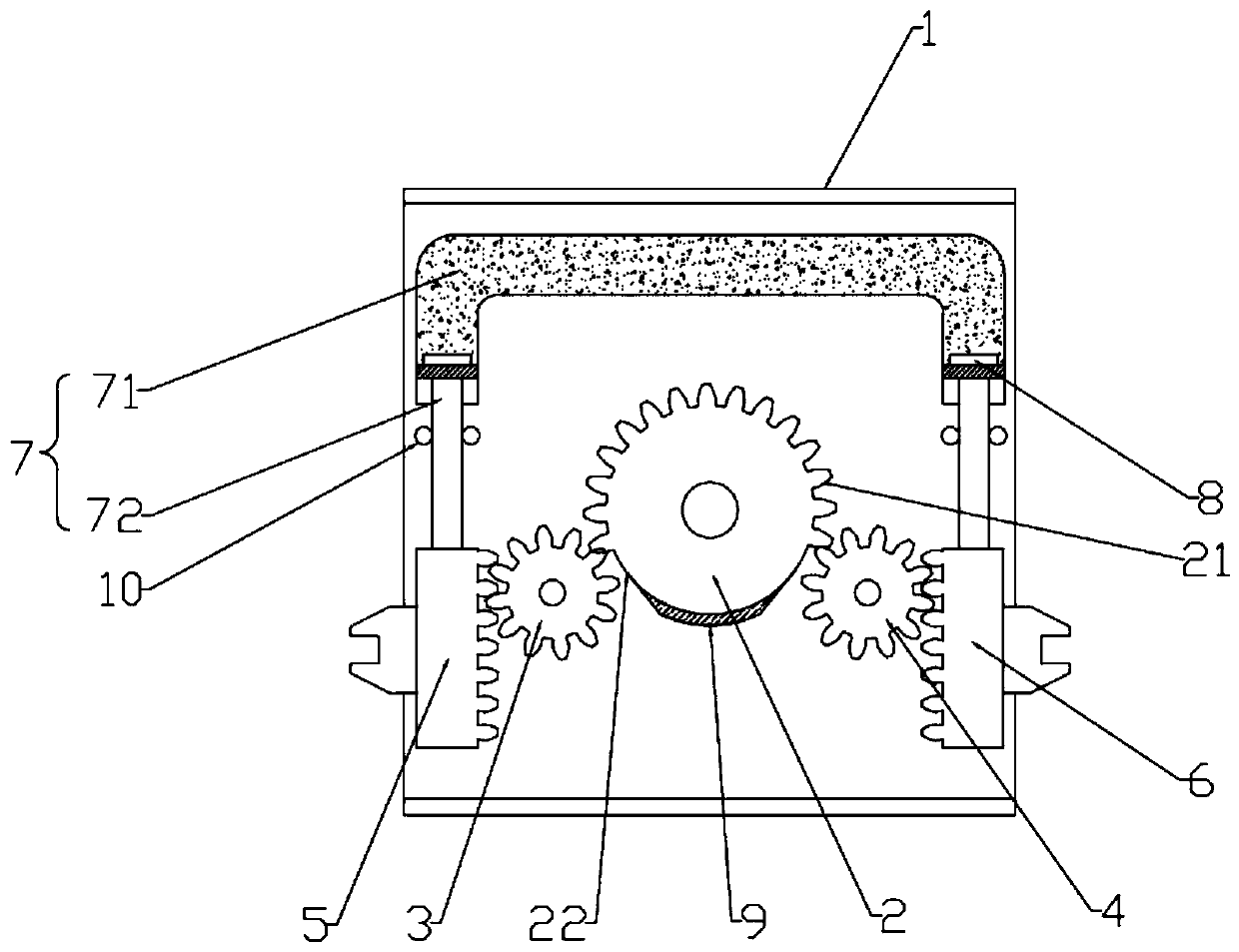
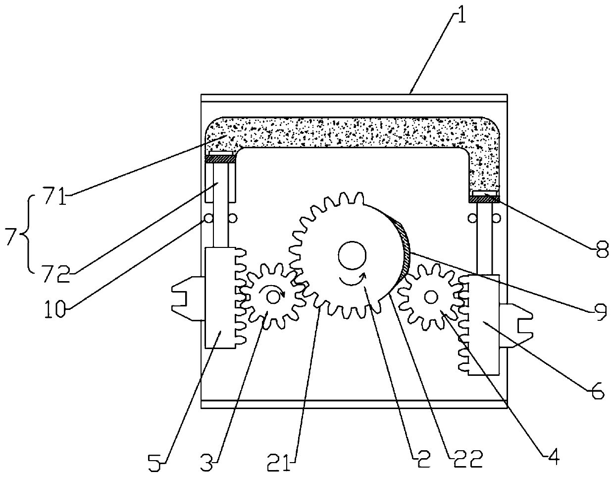
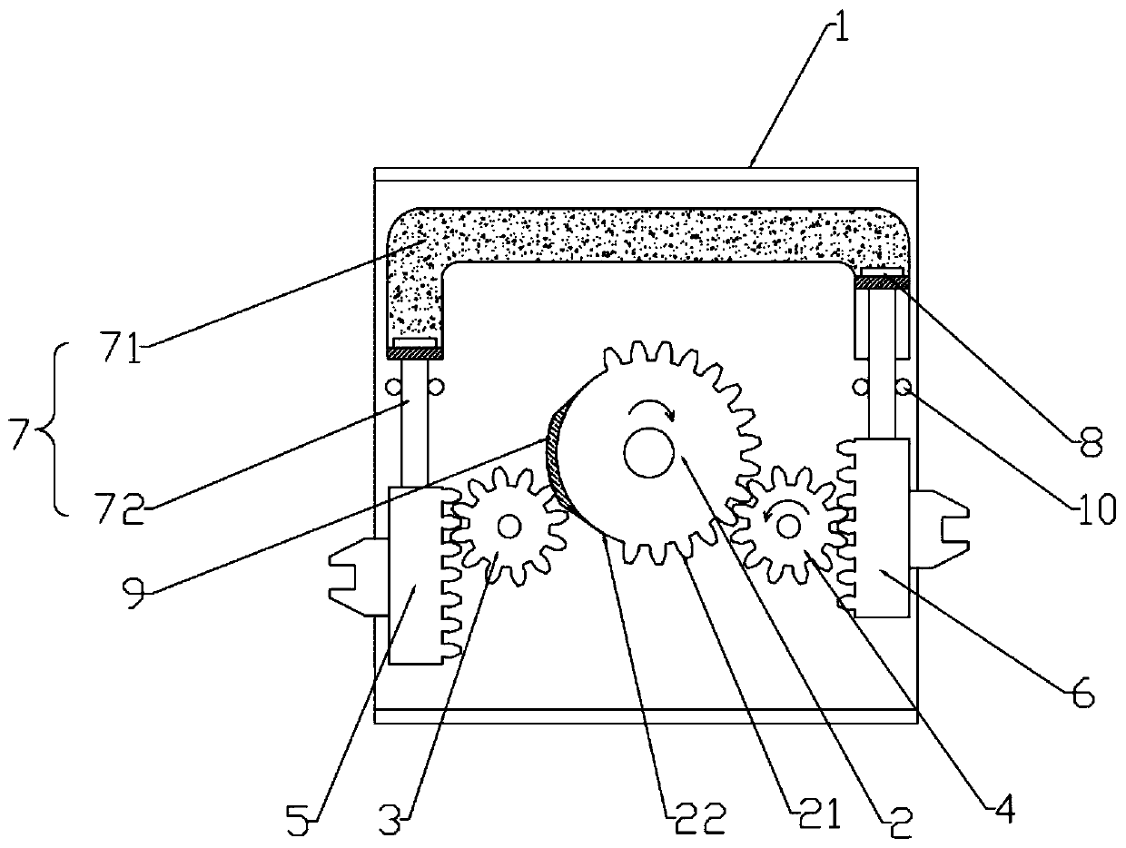
an automatic transfer switch

An automatic transfer switch, transfer switch technology, applied in electric switches, power devices inside switches, contact drive mechanisms, etc., can solve the problems of time-consuming production and assembly, endangering life and property safety, short circuit, etc., and achieve the effect of saving space

Active Publication Date: 2020-04-21
GUANGDONG OWENT ELECTRICAL
View PDF5 Cites 0 Cited by
  • Summary
  • Abstract
  • Description
  • Claims
  • Application Information

AI Technical Summary

Problems solved by technology

In the existing transfer switch, the cooperation between the operating mechanism and the toggle piece is relatively complicated, and there are many parts
Not only is the production and assembly time-consuming, but it is also prone to simultaneous closing of the circuit breakers on both sides, resulting in a short circuit and, in severe cases, endangering the safety of life and property

Method used


Image

  • an automatic transfer switch
  • an automatic transfer switch
  • an automatic transfer switch

Examples


Embodiment Construction

[0021] The present invention will be further described below in combination with specific embodiments. Wherein, the accompanying drawings are only for illustrative purposes, showing only schematic diagrams, rather than physical drawings, and should not be construed as limitations on this patent; in order to better illustrate the embodiments of the present invention, some parts of the accompanying drawings will be omitted, Enlargement or reduction does not represent the size of the actual product; for those skilled in the art, it is understandable that certain known structures and their descriptions in the drawings may be omitted.

[0022] In the drawings of the embodiments of the present invention, the same or similar symbols correspond to the same or similar components; The orientation or positional relationship indicated by etc. is based on the orientation or positional relationship shown in the drawings, which is only for the convenience of describing the present invention ...


PUM


Abstract

The invention provides an automatic change-over switch comprising a mounting bracket, a driving gear, a left driven gear, a right driven gear, a left stirring member, and a right stirring member. Thedriving gear, the left driven gear, the right driven gear, the left stirring member, and the right stirring member are arranged on the mounting bracket. The left and right sides of the driving gear are respectively meshed with the left driven gear and the right driven gear; the left stirring member is meshed with the left driven gear; the right stirring member is meshed with the right driven gear;and one group of circuit breakers us arranged at the outer side of each of the left stirring member and the right stirring member. The driving gear drives the left stirring member and the right stirring member to move up and down alternately to realize changing of opening and closing of the two groups of circuit breakers. The upper parts of the left stirring member and the right stirring member are connected with a locking mechanism. The locking mechanism is used for stopping the simultaneous closing of the left stirring member and the right stirring member. The automatic change-over switch has a simple structure; and because of the locking mechanism, the occurrence of simultaneous closing of the circuit breakers on both sides is prevented effectively.

Description

technical field [0001] The invention relates to the technical field of electrical equipment, in particular to an automatic transfer switch. Background technique [0002] The transfer switch is widely used in various places that require uninterrupted power supply. It realizes the automatic conversion of the load line between the two power sources to ensure the reliability of the user's power supply. In order to realize the opening and closing conversion of two circuit breakers, what the known automatic transfer switch adopted at present is that the toggle brackets on both sides are controlled by the motor to drive the operating mechanism to move up and down alternately, and the toggle brackets drive the opening and closing of the circuit breaker switch. In the existing changeover switch, the cooperation between its operating mechanism and the toggle member is relatively complicated, and there are many parts. Not only is the production and assembly time-consuming, but it is a...

Claims


Application Information

Patent Timeline
Patent Type & Authority Patents(China)
IPC IPC(8): H01H9/26H01H3/24H01H3/40
CPCH01H3/24H01H3/40H01H9/26
Inventor 荣维忠韩先艳刘于庆
Owner GUANGDONG OWENT ELECTRICAL
Why Eureka
Try Eureka