
Explosion-proof device on smelting furnace

An explosion-proof device and smelting furnace technology, applied in the field of smelting furnaces, can solve problems affecting the normal operation of heating furnaces, etc.

Inactive Publication Date: 2019-03-22
许文强
View PDF0 Cites 2 Cited by
  • Summary
  • Abstract
  • Description
  • Claims
  • Application Information

AI Technical Summary

Problems solved by technology

[0002] The explosion-proof device of the smelting furnace is usually an opening on the pipe, and an explosion-proof cover is installed at the opening. When the pressure in the furnace is too high, the explosion-proof cover is opened to protect it. After the pressure in the furnace is normal, the manual operation makes the explosion-proof cover close. However, this kind of explosion-proof device cannot automatically reset and close after the explosion-proof cover is opened, and must be completed manually. operation, so it is necessary to solve these problems

Method used


Image

  • Explosion-proof device on smelting furnace
  • Explosion-proof device on smelting furnace

Examples


Embodiment

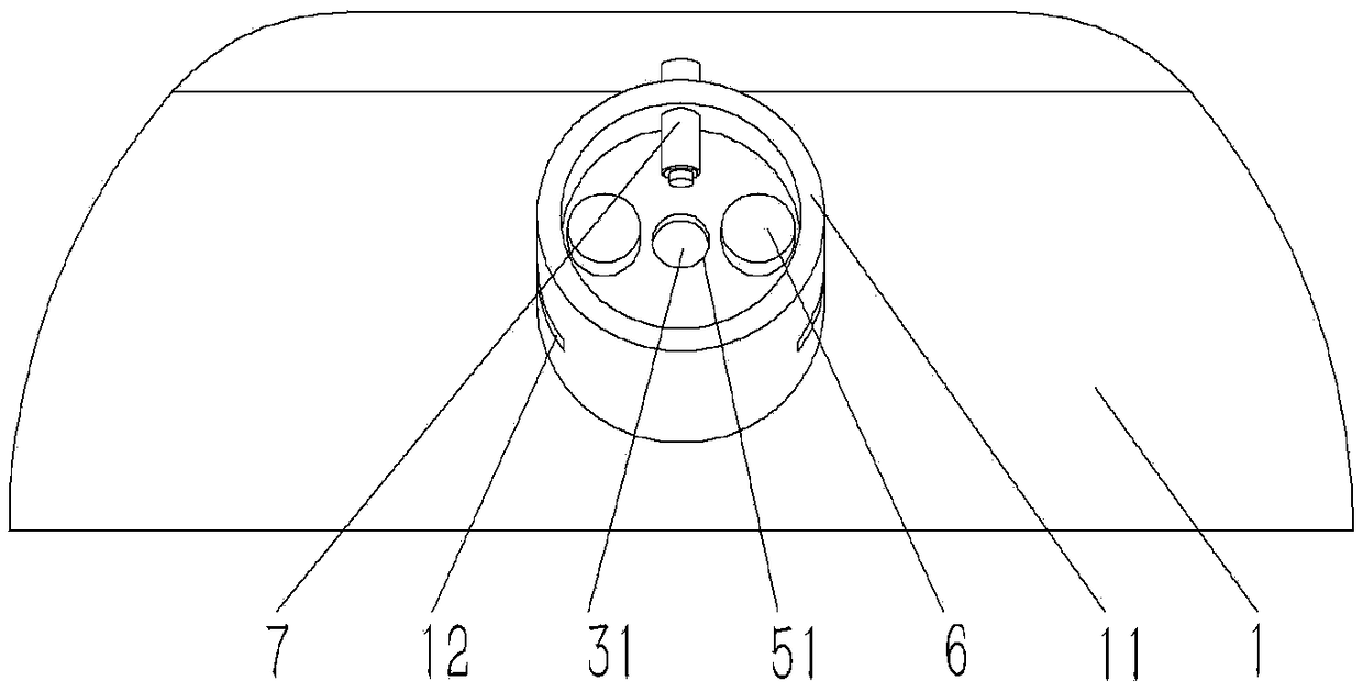
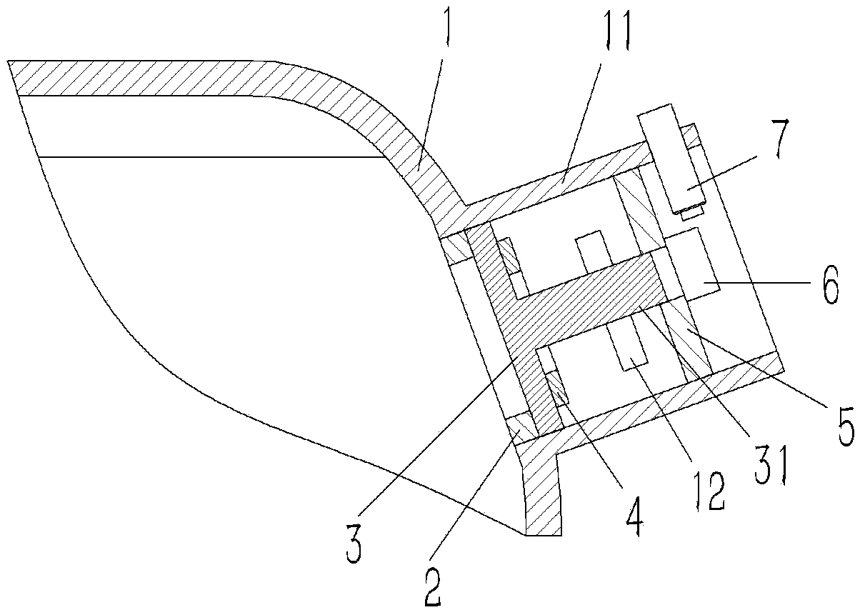
[0014] Example: see figure 1 , 2 As shown, an explosion-proof device on a smelting furnace comprises a furnace body 1 of the smelting furnace, a pressure relief hole is formed on the furnace body 1, and an explosion-proof pipe 11 communicating with the pressure relief hole is formed on the outer wall of the furnace body 1, and the explosion-proof The lower end of the tube 11 is plugged and fixed with a retaining ring 2, and an explosion-proof cover 3 is inserted in the explosion-proof tube 11. The lower end surface of the explosion-proof cover 3 is pressed against the retaining ring 2, and the outer wall of the explosion-proof cover 3 is against the inner wall of the explosion-proof tube 11. Above, the center of the upper end surface of the explosion-proof cover 3 is formed with a guide column 31, and the explosion-proof tube 11 on the upper side of the guide column 31 is inserted and fixed with a positioning plate 5, and the center of the positioning plate 5 is formed with a ...


PUM


Abstract

The invention discloses an explosion-proof device on a smelting furnace. The explosion-proof device comprises a furnace body of the smelting furnace. A pressure relief hole is formed in the furnace body. An explosion-proof pipe communicated with the pressure relief hole is formed on the outer wall of the furnace body. A retaining ring is fixedly inserted into the lower end of the explosion-proof pipe. An explosion-proof cover is inserted in the explosion-proof pipe. The lower end surface of the explosion-proof cover is pressed against the retaining ring. The outer wall of the explosion-proof cover is pressed against the inner wall of the explosion-proof pipe. A guide column is formed in the center of the upper end surface of the explosion-proof cover. A positioning disc is fixedly insertedinto the portion, on the upper side of the guide column, in the explosion-proof pipe. A guide hole is formed in the center of the positioning disc. The guide column of the explosion-proof cover is inserted into the guide hole of the positioning disc. A magnet ring is fixed on the portion, around the guide column, of the upper end face of the explosion-proof cover, electromagnets opposite to the magnet ring are fixed on the upper end face of the positioning disc, and the electromagnets and the magnet ring repel each other. A proximity switch sensor opposite to the guide column is fixedly inserted into the portion, at the upper side of the positioning disc, of the explosion-proof pipe. By the adoption of the explosion-proof device on the smelting furnace, the explosion-proof cover can be automatically closed after explosion-proof pressure relief.

Description

Technical field: [0001] The invention relates to the technical field of smelting furnaces, in particular to an explosion-proof device on the smelting furnace. Background technique: [0002] The explosion-proof device of the smelting furnace is usually an opening on the pipe, and an explosion-proof cover is installed at the opening. When the pressure in the furnace is too high, the explosion-proof cover is opened to protect it. After the pressure in the furnace is normal, the manual operation makes the explosion-proof cover close. However, this kind of explosion-proof device cannot automatically reset and close after the explosion-proof cover is opened, and must be completed manually. operation, so it is necessary to solve these problems. Invention content: [0003] The object of the present invention is to provide an explosion-proof device on a smelting furnace aimed at the deficiencies of the prior art, which can automatically realize the closing of the explosion-proof c...

Claims


Application Information

Patent Timeline
Patent Type & Authority Applications(China)
IPC IPC(8): F27D21/00
CPCF27D21/00F27D2021/0071
Inventor 许文强
Owner 许文强
Learn More