Wall-mounted optical cable cross-connecting box convenient for height adjustment

An optical cable transfer box and wall-mounted technology, which is applied in the field of wall-mounted optical cable transfer boxes, can solve the problems of increasing or decreasing the cost of optical cable transfer boxes, high requirements for installing walls, and reduced reliability, so as to improve safety and reliability, improve The range of installation and use, the possible effect of reducing the drop

Inactive Publication Date: 2021-10-22
杭州普昌科技有限公司
View PDF0 Cites 0 Cited by
  • Summary
  • Abstract
  • Description
  • Claims
  • Application Information

AI Technical Summary

Problems solved by technology

[0003] However, there are great defects in the existing optical cable transfer box during use. The existing optical cable transfer box body is not stable enough to stand, and it is easy to topple before installation, which brings inconvenience to installation and use. At the same time, the transfer box and the The contact surface between the installation walls is not large enough, which will generate overload tension and pressure on the installation walls, which will lead to the insufficient fixing of the optical cable transfer box, which reduces the reliability of use, and the existing optical cable transfer box cannot be adjusted. The size of the installation wall has high requirements, which reduces the scope of installation. At the same time, it cannot be applied to boxes of different sizes, which reduces the compatibility of the optical cable transfer box and brings inconvenience to the subsequent replacement of the box. At the same time, The disassembly is not simple enough, which reduces the convenience of use. The existing optical cable transfer box is not easy to adjust the height. The lines in the optical cable transfer box are bitten, which reduces the safety of use and increases or decreases the cost of putting the optical cable transfer box into use

Method used


Image

  • Wall-mounted optical cable cross-connecting box convenient for height adjustment
  • Wall-mounted optical cable cross-connecting box convenient for height adjustment
  • Wall-mounted optical cable cross-connecting box convenient for height adjustment

Examples


Embodiment Construction

[0036] In order to make the technical means, creative features, goals and effects achieved by the present invention easy to understand, the present invention will be further described below in conjunction with specific embodiments.

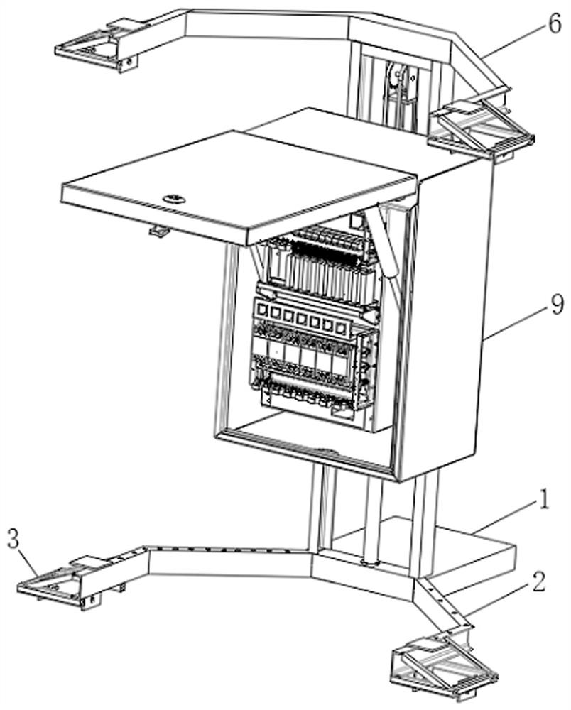
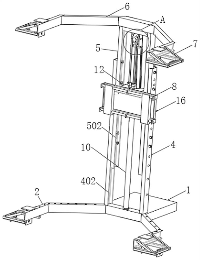
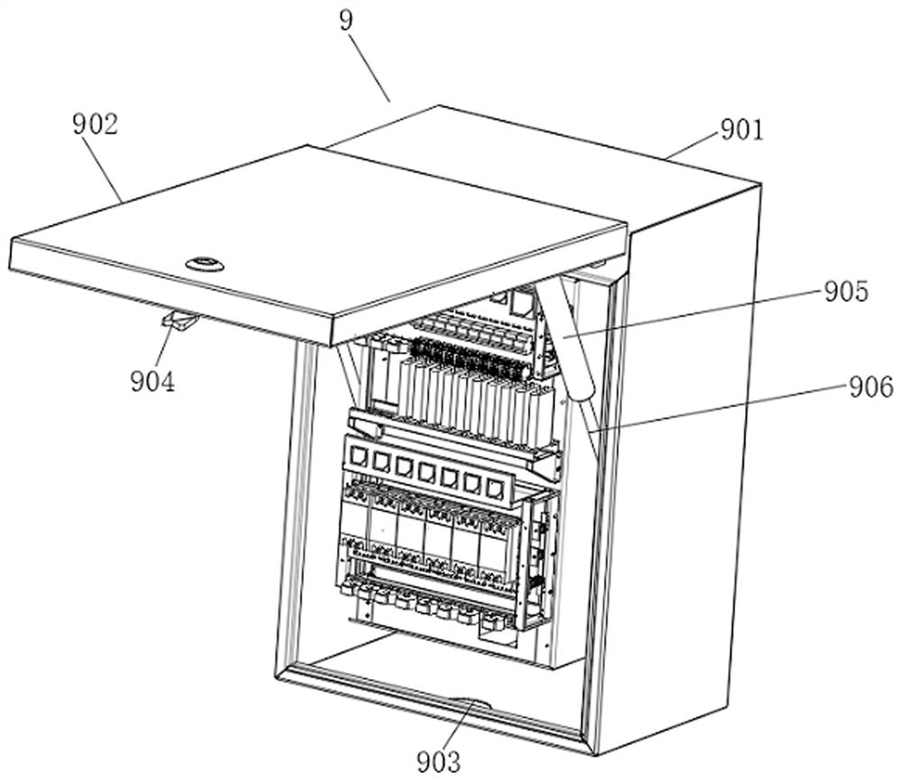
[0037] like Figure 1-Figure 8 As shown, a wall-mounted optical cable transfer box that is convenient for height adjustment according to the present invention includes a bottom plate 1, a bottom frame 2, a support rod 4, a top frame 6 and a box body 9, and the bottom plate 1 is horizontally arranged. By using the bottom plate 1 , to support the optical cable transfer box, so that the optical cable transfer box can be placed on the ground stably before the suspension installation, to avoid the transfer box from tipping over, thereby preventing the confusion of parts in the transfer box, and providing convenience for the installation and use of the transfer box, thereby To improve the convenience of the transfer box installation, one side of the bot...


PUM


Abstract

The invention relates to the technical field of optical cable cross-connecting boxes, in particular to a wall-mounted optical cable cross-connecting box convenient for height adjustment, which comprises a bottom plate, a bottom frame, a supporting rod, a top frame and a box body, a first screw hole is formed in the supporting rod, a second screw hole is formed in a sliding rod, the height of the sliding rod can be adjusted by using a bolt, and the size of the frame body of the optical cable cross-connecting box is further adjusted, so that the optical cable cross-connecting box can be used for mounting walls with different sizes, the mounting and using range of the optical cable cross-connecting box is expanded, and the optical cable cross-connecting box can be adapted to box bodies with different sizes by adjusting the height of the sliding rod, the capacity range of the optical cable cross-connecting box can be adjusted and controlled more flexibly, more choices are provided for actual use requirements, the compatibility of the optical cable cross-connecting box is improved by adapting to box bodies of different sizes, convenience is provided for later replacement, and the service life of the optical cable cross-connecting box is prolonged.

Description

technical field [0001] The invention relates to the technical field of optical cable transfer boxes, in particular to a wall-mounted optical cable transfer box that is convenient for height adjustment. Background technique [0002] The optical cable transfer box is a transfer device that provides cable termination and jumper connection for the backbone layer optical cable and the wiring layer optical cable. Connected with the optical cables in the distribution layer, the optical cable transfer box is a connecting device installed outdoors. The most fundamental requirement for it is to be able to withstand drastic changes in climate and harsh working environments. [0003] However, there are great defects in the existing optical cable transfer box during use. The existing optical cable transfer box body is not stable enough to stand, and it is easy to topple before installation, which brings inconvenience to installation and use. At the same time, the transfer box and the Th...

Claims


Application Information

Patent Timeline
Patent Type & Authority Applications(China)
IPC IPC(8): G02B6/44
CPCG02B6/4446
Inventor 王震史杰波李炯
Owner 杭州普昌科技有限公司
Why Eureka
Try Eureka