A state monitoring device and monitoring method for a bone conduction hearing device

A technology of a condition monitoring device and a hearing device, which is applied to bone conduction transducer hearing equipment, electrical components, etc., can solve the problems of shortening battery life, unable to achieve automatic power saving effect, etc., and achieve the effect of efficient power saving.

Active Publication Date: 2022-03-08
INST OF ACOUSTICS CHINESE ACAD OF SCI
View PDF11 Cites 0 Cited by
  • Summary
  • Abstract
  • Description
  • Claims
  • Application Information

AI Technical Summary

Problems solved by technology

Therefore, in the power-on state of the bone conduction hearing device, when the bone conduction hearing device is removed from the wearer, the power cannot be automatically cut off, the automatic power saving effect cannot be achieved, and the waste of battery power and shortening the service life of the battery cannot be avoided.

Method used


Image

  • A state monitoring device and monitoring method for a bone conduction hearing device
  • A state monitoring device and monitoring method for a bone conduction hearing device
  • A state monitoring device and monitoring method for a bone conduction hearing device

Examples


Embodiment 1

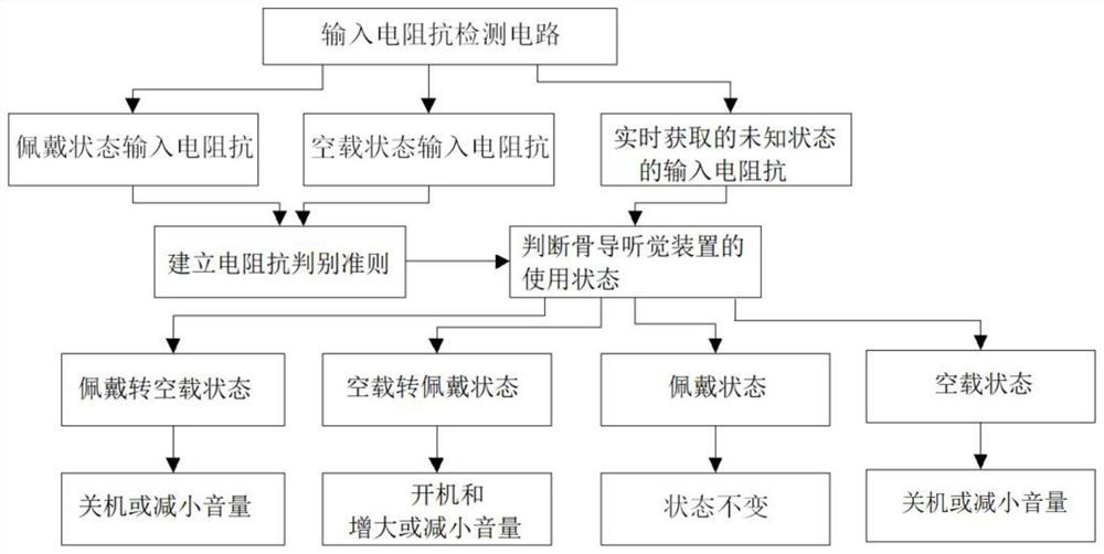
[0084] The present invention also provides a state monitoring method for a bone conduction device, which comprises:

[0085] Step 1) acquired in real time the data acquisition module is provided on the input impedance of the bone-conduction hearing device input impedance detection circuit acquired;

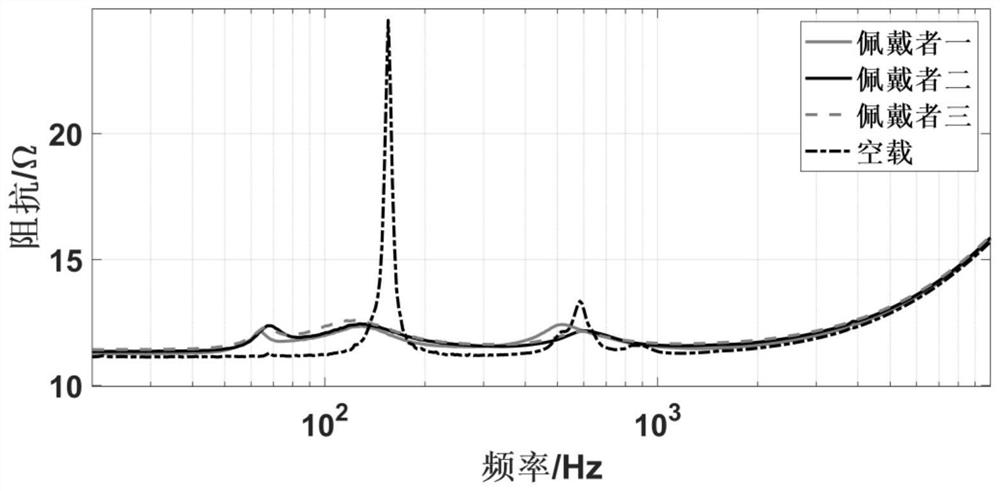
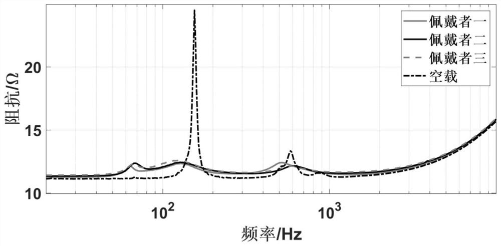
[0086] Size of the input electrical impedance in the idling state and wearing state based on the acquired bone-conduction hearing device. Such as figure 2 , The input impedance of the bone-conduction hearing device substantially fixed at no load In one case, the input impedance due to the different mechanical impedance of the skull rather different subjects in a situation certain uniform wearing state. Different subject to wear at the same time an input impedance of the bone-conduction hearing device is approached in the same position; input impedance and the input impedance of the wearing state when the load is significantly different.

[0087] figure 2 Display more than in the same...

Embodiment 2

[0096] Step 1) The data acquisition module acquires the input electrical impedance collected in the input resistance detection circuit set on the bone conduction device;

[0097] Based on the acquisition of the ingredients and the size of the electrical impedance during the wearing state and the no-load state, the input electrical impedance at the time of no-load is basically fixed in one case, but in the wear state, input resistance resistance due to different The skull impedance of the subject is different without unifying a certain situation. The input electrical impedance is very close to the same bone-conducting device in the same position; and the input resistance resistance in the wear state has a significant difference in input resistance when the no-load.

[0098] Step 2) When the power coupling model of the bone guide audible device is known, when the corresponding parameter is known, the load force impedance of the corresponding pumping bone guide device is obtained by ...


PUM


Abstract

The invention belongs to the technical field of audio communication and state monitoring of bone conduction hearing devices, and in particular relates to a state monitoring device and monitoring method for bone conduction hearing devices. The input electrical impedance collected by the input electrical impedance detection circuit on the bone conduction hearing device; the judgment module is used to judge the wearing state of the bone conduction hearing device in the current state based on the input electrical impedance obtained in real time according to the electrical impedance discrimination criterion ; or according to the load force impedance discrimination criterion, based on the load force impedance acquired in real time, judging the wearing state of the bone conduction hearing device in the current state; and a state monitoring module, used to monitor the wearing state of the bone conduction hearing device according to the judgment result, Turn on and off the bone conduction hearing device and adjust the volume to complete the state monitoring of the bone conduction hearing device.

Description

Technical field [0001] In the field of state monitoring techniques of audio communication and bone conduction apparatus, the present invention is, in particular, to a state monitoring apparatus for bone conduction detection devices and a monitoring method. Background technique [0002] In order to protect the health of national listening, auditory equipment independent technology development capabilities still need to be enhanced. The promotion of bone conduction devices will become an effective supplement of traditional gas conductivity headphones, support technological advances in hearing recovery and wearable devices. Bone-guided auditory technology passes the outer sound wave to the inner ear, which insensibily perceive the external sound, and is unpacked, and it is easy to have a strange advantage. However, compared to the theoretical technology of air passage-leading headphones, the theoretical technology of bone conduction auditors is far less mature, and there are many sc...

Claims


Application Information

Patent Timeline
Patent Type & Authority Patents(China)
IPC IPC(8): H04R29/00
CPCH04R29/00H04R2460/13
Inventor 桑晋秋王杰聂亚飞张芳杰郑成诗李晓东
Owner INST OF ACOUSTICS CHINESE ACAD OF SCI
Why Eureka
Try Eureka