Display module and display device

A technology of display module and display area, used in static indicators, static memory, instruments, etc., can solve the problems of uneven wiring resistance and uneven brightness of scan lines

Active Publication Date: 2019-03-22
HKC CORP LTD
View PDF16 Cites 13 Cited by
  • Summary
  • Abstract
  • Description
  • Claims
  • Application Information

AI Technical Summary

Problems solved by technology

[0004] The main purpose of the present invention is to provide a display module and a display device, aiming to solve the problem of uneven brightness due to the uneven resistance of the scanning lines between the area far away from the gate driver and the area close to the gate driver of the display panel. question

Method used


Image

  • Display module and display device
  • Display module and display device
  • Display module and display device

Examples


Embodiment Construction

[0035] The following will clearly and completely describe the technical solutions in the embodiments of the present invention with reference to the accompanying drawings in the embodiments of the present invention. Obviously, the described embodiments are only part of the embodiments of the present invention, not all of them. Based on the embodiments of the present invention, all other embodiments obtained by persons of ordinary skill in the art without creative efforts fall within the protection scope of the present invention.

[0036] It should be noted that if there is a directional indication (such as up, down, left, right, front, back...) in the embodiment of the present invention, the directional indication is only used to explain the position in a certain posture (as shown in the accompanying drawing). If the specific posture changes, the directional indication will also change accordingly.

[0037] In addition, if there are descriptions involving "first", "second" and ...


PUM


Abstract

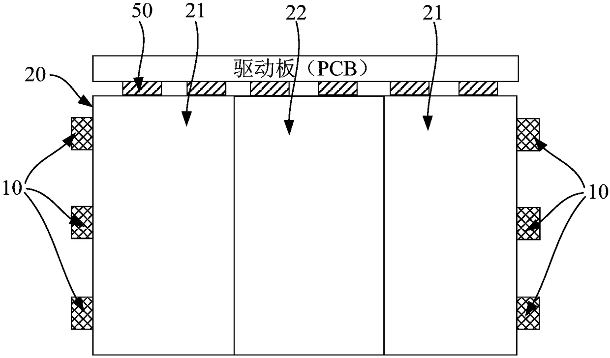
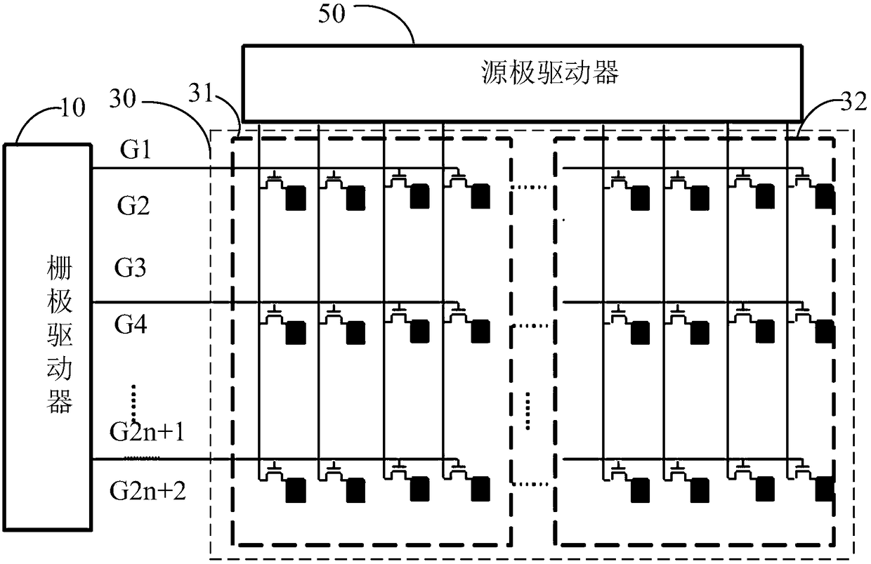
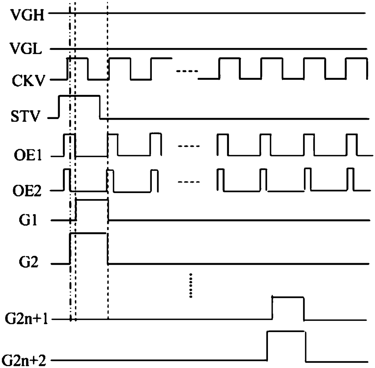
The invention discloses a display module and a display device. The display module comprises a gate driver, a display panel, and a thin film transistor array, wherein the gate driver comprises a plurality of first output ends and second output ends; the display panel is provided with a first display area disposed adjacent to the gate driver and a second display area disposed away from the gate driver; the thin film transistor array includes a plurality of rows of first thin film transistors disposed in the first display area and a plurality of rows of second thin film transistors disposed in the second display area; the plurality of first output ends are in one-to-one correspondence connection with gates of the plurality of rows of first thin film transistors through an odd number of rows of scanning lines; the plurality of second output ends are in one-to-one correspondence connection with gates of the plurality of rows of second thin film transistors through an even number of rows ofscanning lines; and the on-time of the first thin film transistor is smaller than that of the second thin film transistor on the same line. According to the display module and the display device, theproblem of uneven brightness caused by unevenness of scanning line trace resistance of the area of the display panel away from the gate driver and the area of the display panel close to the gate driver is solved.

Description

technical field [0001] The invention relates to the technical field of electronic circuits, in particular to a display module and a display device. Background technique [0002] In order to comply with the development of large-scale and high-resolution LCD TVs, more and more liquid crystal display panels adopt a narrow bezel design. [0003] However, the gate driver is generally arranged at the side frame of the display panel, so that equal-resistance wiring cannot be set between each scan line and the gate driver, that is, the wiring between the scan line near the gate driver and the gate driver Shorter, lower resistance, longer traces and higher resistance between the scan line and the gate driver at the position away from the side edge, resulting in uneven charging between the area far from the gate driver and the area close to the gate driver on the panel The problem. Contents of the invention [0004] The main purpose of the present invention is to provide a display...

Claims


Application Information

Patent Timeline
Patent Type & Authority Applications(China)
IPC IPC(8): G09G3/36G11C19/28
CPCG09G3/3611G09G3/3677G09G2310/0286G09G2320/0233G11C19/28
Inventor 王明良
Owner HKC CORP LTD
Why Eureka
Try Eureka