Electromagnetic MEMS micromirror

A micromirror and electromagnetic technology, applied in the field of electromagnetic MEMS micromirrors, can solve the problems of difficult combination of MEMS micromirrors, unsuitable for mass production, insufficient electromagnetic driving force, etc.

Pending Publication Date: 2019-03-26
苏州希景微机电科技有限公司
View PDF6 Cites 9 Cited by
  • Summary
  • Abstract
  • Description
  • Claims
  • Application Information

AI Technical Summary

Problems solved by technology

Piezoelectric-driven MEMS micromirrors are difficult to combine with MEMS technology and are not suitable for mass production
[0004] The existing electromagnetic MEMS micromirror, when the size of the mirror surface is large, generally works in a resonance state to meet the large scanning angle, and cannot realize static scanning; at the same time, the electromagnetic driving force is insufficient, and it cannot perform large-angle deflection to complete raster scanning; movable Coil-stationary magnet electromagnetically driven MEMS micromirror, the manufacturing process is complicated and the cost is high; when the micromirror works for a long time or is driven by a large current, the heat generated will cause the resonant frequency of the micromirror to drift, and in severe cases it will cause the micromirror Damage (coil oxidation due to excessive heat generation)

Method used


Image

  • Electromagnetic MEMS micromirror
  • Electromagnetic MEMS micromirror
  • Electromagnetic MEMS micromirror

Examples


Embodiment 1

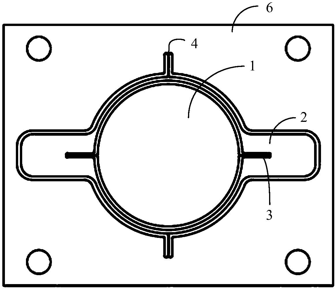
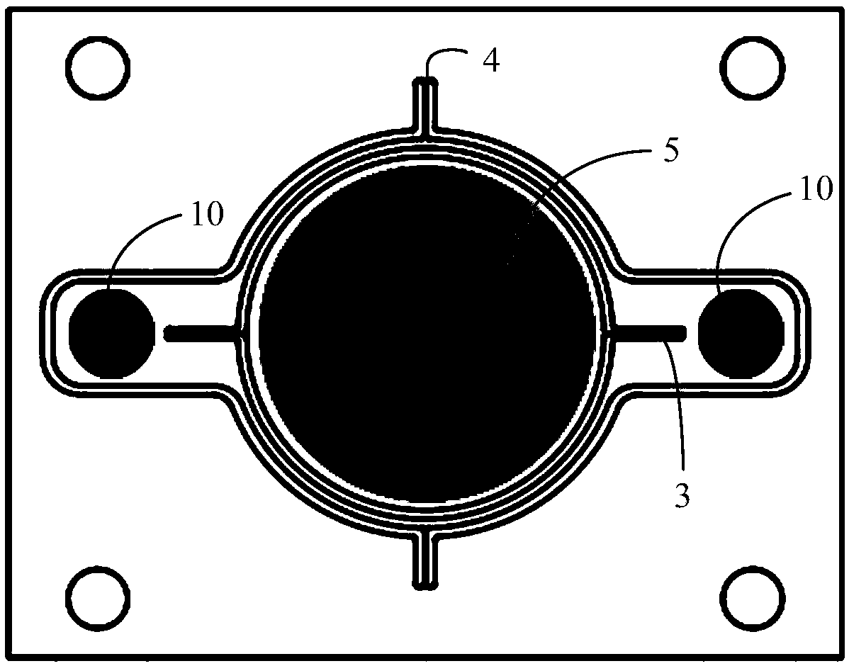
[0031] Such as Figure 2-3 As shown, the electromagnetic MEMS micromirror includes a frame 2, and a mirror 1 is also arranged in the frame 2. The mirror 1 is connected to the inside of the frame 2 through a first rotating shaft 3, and a second rotating shaft 4 is arranged outside the frame 2, and the back of the mirror 1 is arranged There is a soft magnetic film 5. The outside of the frame 2 is connected to the base plate 6 through the second rotating shaft 4 , and the directions of the first rotating shaft 3 and the second rotating shaft 4 are arranged to cross. The frame 2, the first rotating shaft 3 and the second rotating shaft 4 are all made of single crystal silicon.

[0032] The monocrystalline silicon material has a simple structure and fewer internal defects. The internal damping of the rotating shaft structure is small during motion, and the Q value (that is, the quality factor) is greatly improved, which can reach 1000; when the rotating shaft structure is composed...


PUM


Abstract

The invention discloses an electromagnetic MEMS micromirror comprising a frame. A mirror surface is arranged in the frame and is connected with the inner side of the frame by a first rotating shaft; asecond rotating shaft is also arranged at the outer side of the frame; and a soft magnetic film is arranged at the back of the mirror surface. According to the electromagnetic MEMS micromirror, the electromagnetic force generated by the soft magnetic film and a first driving coil with a magnetic core are provided as a driving force for the first rotating shaft being a quick shaft; and the electromagnetic force generated by a permanent magnet and a second driving coil is provided as a driving force for the second rotating shaft being a slow shaft. Therefore, grating scanning is realized; the quick shaft scanning frequency is increased; and the static drive control for the slow shaft is realized.

Description

technical field [0001] The invention relates to the field of microelectromechanical systems, in particular to an electromagnetic MEMS micromirror. Background technique [0002] MEMS micromirror is an optical device based on micro-nano processing technology. Its basic principle is as follows: figure 1 , that is, the mirror is twisted or deformed under the force of the micro-drive structure, and the propagation direction of the beam is changed by the deflection of the micro-mirror at a certain angle. Photoelectric technologies such as laser projection, lidar, three-dimensional scanning, and MEMS optical switches have become research hotspots. Among them, MEMS micromirrors, as key components, are of great significance to the development and research of related technologies. MEMS micromirrors have the advantages of fast scanning speed, compact structure, and good mechanical properties. They have important applications in the fields of barcode recognition, laser communication, f...

Claims


Application Information

Patent Timeline
Patent Type & Authority Applications(China)
IPC IPC(8): G02B26/08G02B26/10
CPCG02B26/085G02B26/101
Inventor 李帆雅
Owner 苏州希景微机电科技有限公司
Why Eureka
Try Eureka