Radar antenna protection channel generation method

A technology for protecting channels and radar antennas, applied in radio wave measurement systems, instruments, etc., can solve problems such as poor antenna sidelobe interference, strong clutter suppression effect, no protection antenna for antennas, and difficult precise selection of protection channel parameters, etc., to achieve has the effect of correctness

Active Publication Date: 2019-03-29
成都汇蓉国科微系统技术有限公司
View PDF4 Cites 4 Cited by
  • Summary
  • Abstract
  • Description
  • Claims
  • Application Information

AI Technical Summary

Benefits of technology

This patented technology allows creating an accurate protective path around certain types of radio waves without causing any unwanted signals from other sources or objects nearby. Its results help prevent damage caused by these radiation patterns over time.

Problems solved by technology

This patented technical problem addressed in the current literature relates to improving the performance of radio frequency (RF) communication systems that use multiple transmitting/receiving devices connected together with an integrated circuit chip called a transponder. These arrangements can be used at different frequencies depending on their needs. Existing solutions involve adding extra components like filters between each device's transmitter and receivers, resulting in reduced efficiency due to increased complexity and cost associated with these added parts. Therefore, the objective of the present solution involves developing a more efficient way to protect against electromagnetic interference without requiring any changes made during manufacturing processes.

Method used


Image

  • Radar antenna protection channel generation method
  • Radar antenna protection channel generation method
  • Radar antenna protection channel generation method

Examples


Embodiment Construction

[0027] Specific embodiments of the present invention will be described in detail below in conjunction with the accompanying drawings.

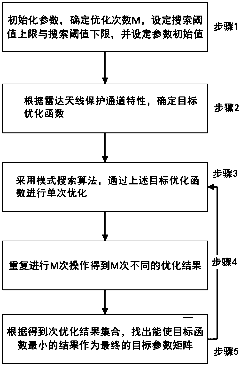
[0028] The invention provides a method for generating a radar antenna protection channel. The method is based on a pattern search algorithm and is used to obtain design parameters of the radar antenna protection channel. Such as figure 1 As shown, the method includes the following steps:

[0029] Step 1: Determine initialization parameters

[0030] The radar antenna protection channel is represented by a parameter matrix x, the dimension of the parameter matrix x is equal to the dimension of the antenna element, and the initial value of the parameter matrix x is set 0 .

[0031] In the embodiment of the present invention, the antenna array element is selected as a 4 × 2-dimensional planar array. When the antenna array element is located under the Cartesian plane coordinate system x-y, the number of array elements distributed in the x direct...


PUM


Abstract

The present invention provides a radar antenna protection channel generation method. The method comprises the following steps: Step 1: determining an initialization parameter (wherein the protection channel parameter matrix is an NxM-dimensional matrix equal to the dimension of the antenna array element), and setting the initial value of the parameter matrix; Step 2: determining the objective optimization function according to the characteristics of the radar antenna protection channel; Step 3: using the pattern search algorithm to perform single optimization through the objective optimizationfunction; Step 4: repeating the step 3 operation for M times to obtain a set of M times optimization results; and Step 5: in the set of M times optimization results, finding out an optimization result that can minimize the objective optimization function to generate an antenna protection channel. The protection channel generation parameters obtained by using the method provided by the present invention have correctness, effectiveness and reliability; and the protection channel generated according to the parameters can effectively suppress the side antenna interference and various strong clutter echoes.

Description


Claims


Application Information

Patent Timeline
Owner 成都汇蓉国科微系统技术有限公司
Why Eureka
Try Eureka