Thyristor rigger strobe configuration circuit

A technology for configuring circuits and thyristors, applied in the direction of adjusting electrical variables, control/regulating systems, instruments, etc., to achieve the effect of strengthening protection

Active Publication Date: 2019-04-02
东莞市骏宏电子科技有限公司
View PDF3 Cites 0 Cited by
  • Summary
  • Abstract
  • Description
  • Claims
  • Application Information

AI Technical Summary

Problems solved by technology

[0004] In order to solve the problems existing in the existing compensated AC voltage stabilizer, the present invention provides a thyristor trigger gating configuration circuit including a diode trigger configuration matrix, according to the input trigger gating control value, through the diode trigger configuration matrix to output The trigger control signal is controlled to realize the control of the on-off combination state of the thyristor in the thyristor switch group; the trigger gating control value is an M-bit binary value; the diode trigger configuration matrix can be configured to change the value of each trigger gating control value. The on-off combination corresponding to the on-off combination state of the thyristor in the thyristor switch group; in the M-bit binary value of the trigger gating control value, there is one and only one effective

Method used


Image

  • Thyristor rigger strobe configuration circuit
  • Thyristor rigger strobe configuration circuit
  • Thyristor rigger strobe configuration circuit

Examples


Embodiment Construction

[0039] In the following, the present invention will be further described through the application of the thyristor trigger gate configuration circuit in the AC voltage stabilizer in conjunction with the accompanying drawings.

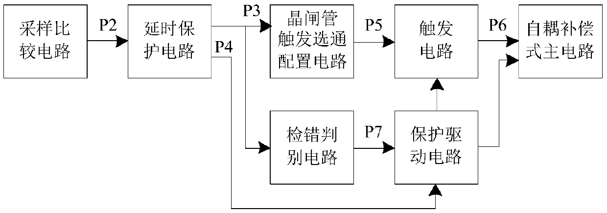
[0040] figure 1 It is a block diagram of an AC voltage stabilizer. The sampling comparison circuit performs voltage sampling on the AC power supply voltage, and outputs the trigger gating control value P2; the delay protection circuit inputs the trigger gating control value P2, and outputs the delayed trigger gating control value P3 and The non-trigger zone control signal P4; the thyristor trigger gating configuration circuit inputs the delayed trigger gating control value P3, and outputs the trigger control signal P5; the trigger circuit sends the trigger signal P6 to the self-coupling compensation type master according to the input trigger control signal P5 The circuit controls the on-off of the bidirectional thyristor in the thyristor switch group; th...


PUM


Abstract

A thyristor trigger strobe configuration circuit is used for controlling an on-off combination of a thyristor in a thyristor switch group; a corresponding trigger control signal is selected and enabled according to a trigger strobe control value through a diode trigger configuration matrix to control the on-off combination state of the thyristor in the thyristor switch group. When the thyristor trigger strobe configuration circuit is used in an alternating current voltage stabilizer, voltage sampling is performed on an alternating current power supply voltage by a sampling comparison circuit to output the trigger strobe control value; the thyristor trigger strobe configuration circuit outputs the trigger control signal according to the delayed trigger strobe control value, and the on-off of the thyristor in the thyristor switch group is controlled by the trigger circuit; when interlock control is implemented, open circuit protection for the thyristor switch group is started or stoppedby an error detection determination circuit and a protection drive circuit according to whether the trigger strobe control value is valid or not, and the power supply of the trigger circuit is controlled, thereby effectively strengthening the protection degree for abnormality in the working process.

Description

technical field [0001] The invention relates to the technical field of power supplies, in particular to a thyristor trigger gate configuration circuit. Background technique [0002] The existing compensated AC voltage stabilizer has the advantages of wide voltage stabilization range, almost no waveform distortion, high overall efficiency and strong load adaptability. The principle is to automatically control the switching of different winding coils of the primary winding on the compensation transformer according to the level of the input voltage, using the ratio relationship between the primary side working winding and the secondary winding, or by adjusting the voltage applied to the primary winding , providing bidirectional and multi-level voltage compensation, so as to achieve the purpose of voltage regulation and stabilization. [0003] At present, controllers such as single-chip microcomputers and PLCs are mainly used to judge the level of input voltage and partition th...

Claims


Application Information

Patent Timeline
Patent Type & Authority Applications(China)
IPC IPC(8): G05F1/20
CPCG05F1/20
Inventor 刘建华凌云文定都王兵
Owner 东莞市骏宏电子科技有限公司
Why Eureka
Try Eureka