Cooling system with adjustable internal heat exchanger

A technology for internal heat exchangers, cooling systems, applied in refrigerators, refrigeration components, refrigeration and liquefaction, etc., can solve problems such as limiting IHX performance, achieve constant conditions, low flow rate, and improve flow control.

Inactive Publication Date: 2019-04-02
EATON INTELLIGENT POWER LIMITED
View PDF6 Cites 0 Cited by
  • Summary
  • Abstract
  • Description
  • Claims
  • Application Information

AI Technical Summary

Problems solved by technology

Therefore, the maximum compressor temperature also limits the maximum possible IHX performance

Method used


Image

  • Cooling system with adjustable internal heat exchanger
  • Cooling system with adjustable internal heat exchanger
  • Cooling system with adjustable internal heat exchanger

Examples


Embodiment Construction

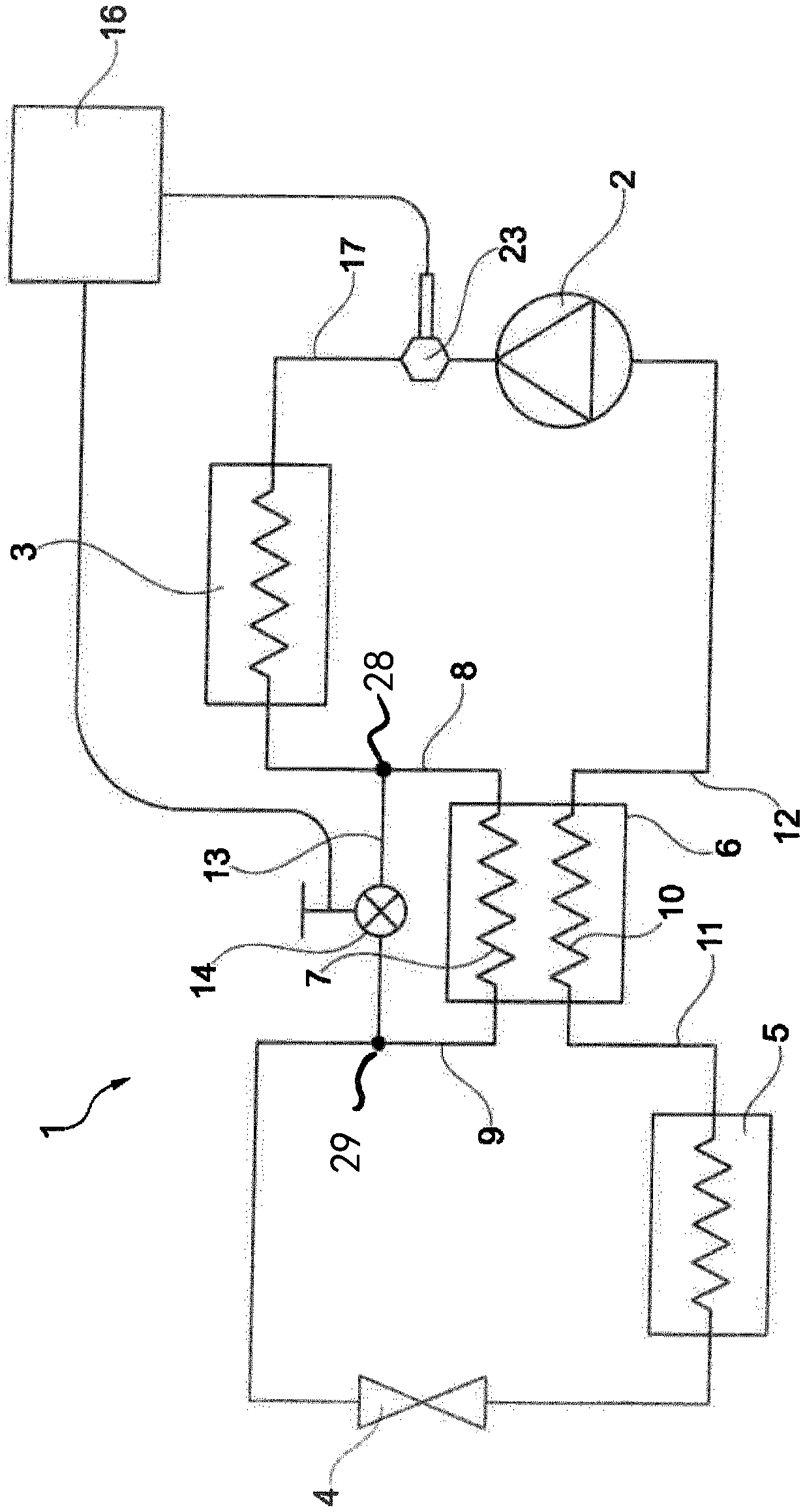
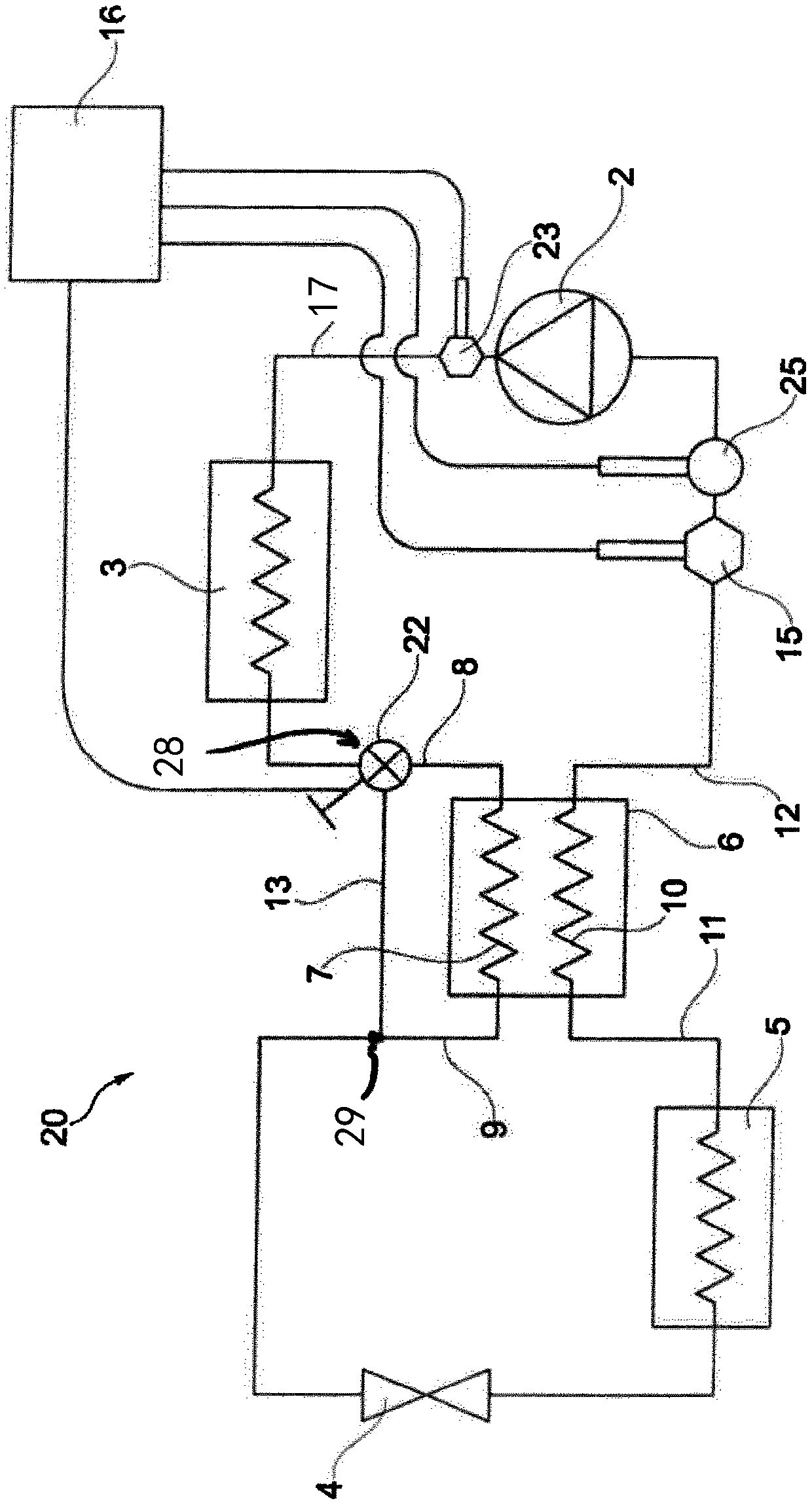
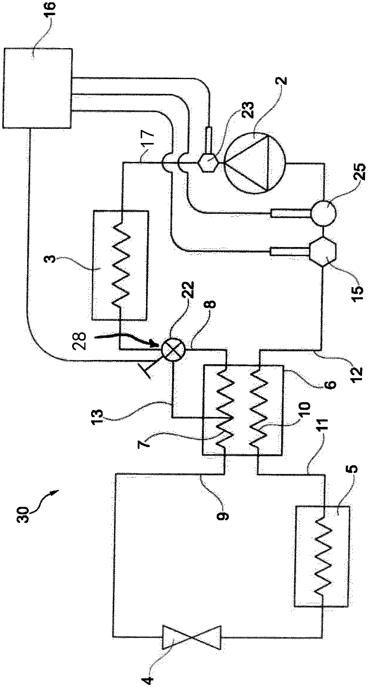
[0064] figure 1 A cooling system 1 is schematically shown comprising a compressor 2 , a condenser 3 , an expansion valve 4 and an evaporator 5 connected in sequence by fluid lines in a circuit.

[0065] In order to further improve the cooling system 1, the internal heat exchanger 6 is provided with a first conduit 7 arranged in the lines 8, 9 between the condenser 3 and the expansion valve 4, and a first conduit 7 arranged between the evaporator 5 and the compressor 2 Second conduit 10 in lines 11 , 12 .

[0066] Furthermore, a bypass fluid line 13 with a controllable valve 14 is arranged between the line 8 and the line 9 , ie between the two ends of the first conduit 7 of the internal heat exchanger 6 . The bypass fluid line 13 is arranged between the inlet connection 28 and the outlet connection 29 .

[0067] The fluid line 8 between the condenser 3 and the first conduit 7 of the internal heat exchanger 6 is permanently open. The first conduit 7 of the internal heat excha...


PUM


Abstract

The invention relates to a cooling system comprising, connected in a loop by fluid lines and in succession, a compressor, a condenser, an expansion valve and an evaporator, further comprising an internal heat exchanger having a first conduit in heat exchanging contact with a second conduit, wherein the first conduit is part of the fluid line between the condenser and the expansion valve and wherein the second conduit is part of the fluid line between the evaporator and the compressor, further comprising a bypass fluid line arranged between the two ends of the first conduit of the internal heatexchanger.

Description

technical field [0001] The invention relates to a cooling system comprising a compressor, a condenser, an expansion valve and an evaporator connected in sequence through a fluid line in a circuit, the cooling system also comprising an internal heat exchanger having a A first pipe in heat exchange contact of the two pipes, wherein the first pipe is part of the fluid line between the condenser and the expansion valve, and wherein the second pipe is part of the fluid line between the evaporator and the compressor. Background technique [0002] Such a cooling system is known, for example, from EP1043550. This publication describes a cooling system in which a fluid (in particular CO2) is used which becomes supercritical in a high-pressure line between the compressor and the expansion valve. The pressure in the high pressure line may vary due to the cooling effect of the condenser. In particular, this variation depends on the ambient temperature. In cold weather, the fluid in t...

Claims


Application Information

Patent Timeline
Patent Type & Authority Applications(China)
IPC IPC(8): F25B40/00F25B41/04F25B49/02
CPCF25B49/02F25B2309/061F25B2600/2501F25B2700/1931F25B2700/1933F25B2700/21151F25B41/20F25B2700/21152
Inventor L·沃特
Owner EATON INTELLIGENT POWER LIMITED
Why Eureka
Try Eureka