screw pump
What is Al technical title?
Al technical title is built by PatSnap Al team. It summarizes the technical point description of the patent document.
A screw pump and screw technology, applied in the direction of pumps, pump components, rotary piston pumps, etc., can solve problems such as difficult alignment, cumbersome installation, and difficulty in pushing a bush or multiple bushes to the end of the screw, etc. , to achieve the effect of gap equalization compensation
Active Publication Date: 2021-05-11
LEISTRITZ PUMPEN
View PDF3 Cites 0 Cited by
Summary
Abstract
Description
Claims
Application Information
AI Technical Summary
This helps you quickly interpret patents by identifying the three key elements:
Problems solved by technology
Method used
Benefits of technology
Problems solved by technology
[0004] Fitting and centering bushings that are floating in the unloaded state is very tedious because especially when setting two idler screws it is difficult to get one or both bushings in proper alignment with the ends of the screws and due to For this reason, it is very difficult to push a bushing or bushings onto the end of the screw, which usually requires several attempts to achieve
Method used
Image
Click on the blue label to locate the original text in one second.
Reading with bidirectional positioning of images and text.
Examples
Embodiment Construction
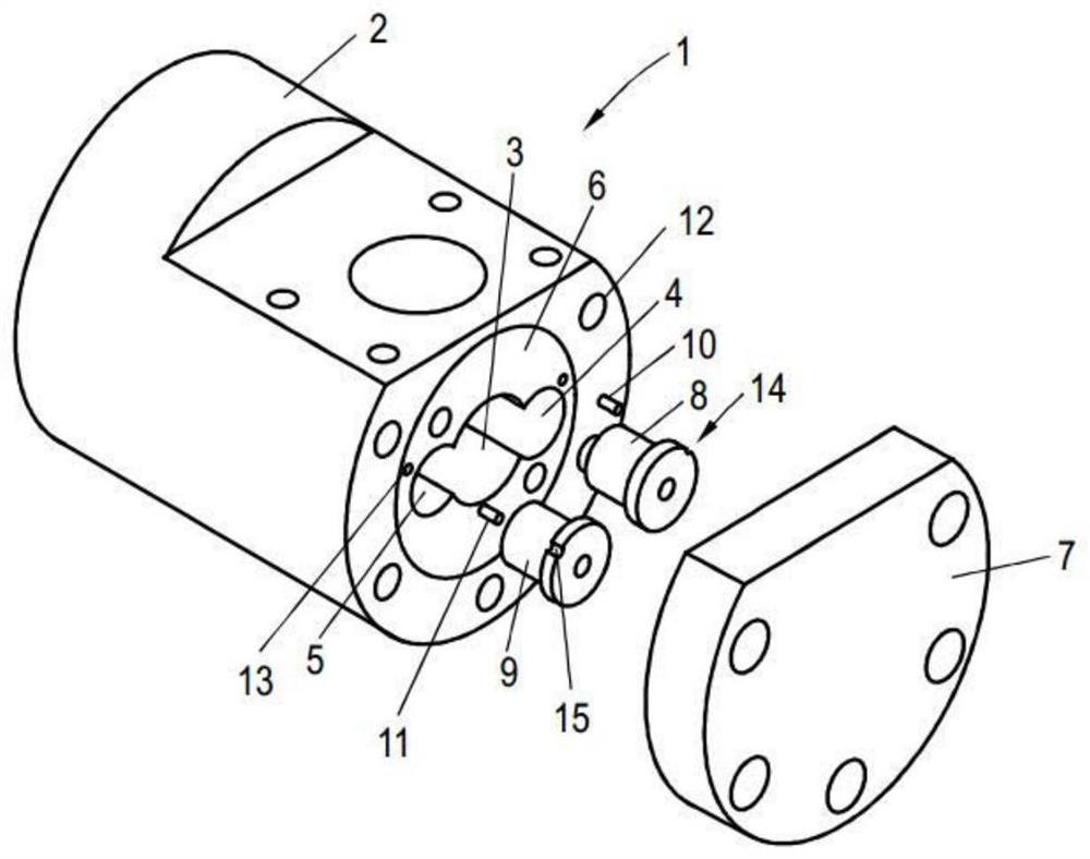
[0037] figure 1 A partially exploded view of a screw pump 1 according to the invention is shown. Shown is a housing 2 in which a first hole 3 for fixing the drive screw is formed in the middle of the housing 2 and two additional holes 4, 5 laterally offset from the first hole 3 are formed in the housing, Each additional hole accommodates an idler screw which engages the drive screw. The screw is not shown therein. The bores 4 , 5 for fastening the idler screws extend as far as they are directly flush with the end face 6 of the housing 2 .
[0038] Also shown is a housing cover 7 which is tightly screwed onto the housing 2 by means of suitable fastening screws to close it.
[0039] Also shown are two bushings 8,9, which are part of the hydraulic thrust compensation system, by which the two idler screws are axially supported. The design and function of the bushings 8,9 will be further discussed next. Two pins 10,11 are used to fix the bushing in place non-rotatably; one end...
PUM
Abstract
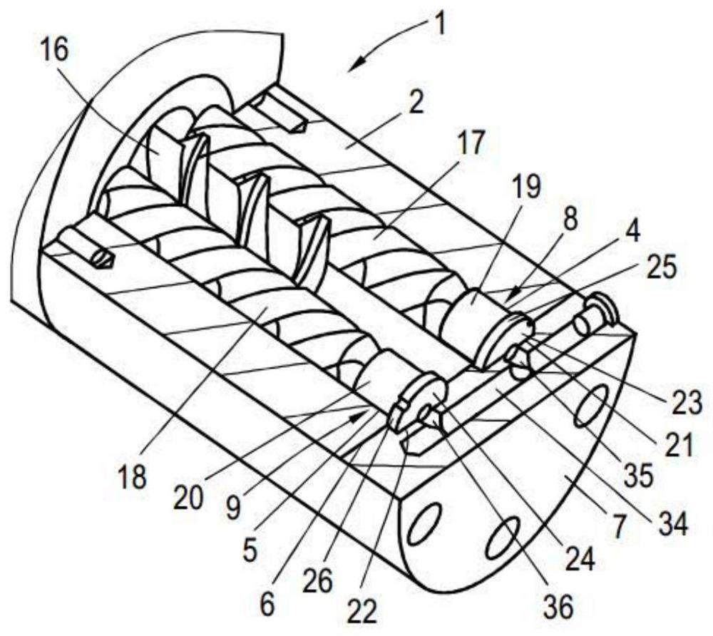
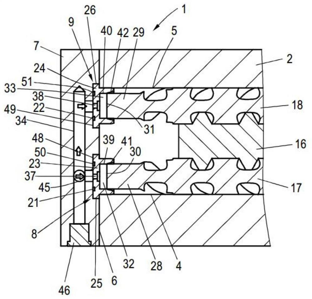
A screw pump having a housing (2); a housing cover (7); at least one idler screw (17,18) fixed in a hole (4,5) in the housing (2) ; and a bushing (8,9), which is arranged on the housing cover (7), the housing cover (7) has a receiving space (32,33) limited by the cylindrical flange (19,20), the inertia One end (29) of the wheel screw (17,18) engages in said cylindrical flange (19,20), wherein the bushing (8,9) has an opening (37,38) at its bottom, under pressure The fluid supplied by the feed channel (34) in the cover is fed from the opposite end of the idler screw (17,19) to the end face (30,31) of the idler screw (17,18) through the above-mentioned opening (37,38). ), where the bushings (8,9) engage with radial clearances in the housings (21,22) in the cover and include radial flanges (25,26) through which the bushings pass Axially supported on the housing (2) and in which at least a portion of the bushings (8,9) the annular flanges (25,26) engage in the bores (4,5) and are accommodated in the bores with some clearance.
Description
technical field [0001] The invention relates to a screw pump with a housing, a housing cover, at least one idler screw accommodated in a bore of the housing and a bushing arranged on the housing cover, the bushing having a cylindrical The flange defines a receiving space in which one end of the idler screw engages, and the bottom of the bushing has an opening through which fluid supplied by the feed channel in the cover can be passed under pressure from the opposite side of the idler screw. One end feeds into the end face of the idler screw. Background technique [0002] Screw pumps are used to transport various fluid media. Progressive cavity pumps consist of a housing with at least two screws, a drive screw and at least one idler screw driven by the drive screw, however, often two idler screws are provided, one of which is arranged in the center of the drive either side of the screw. After the screws engage each other, one or more idler screws are driven by the drive sc...
Claims
Application Information
Patent Timeline
Application Date:The date an application was filed.
Publication Date:The date a patent or application was officially published.
First Publication Date:The earliest publication date of a patent with the same application number.
Issue Date:Publication date of the patent grant document.
PCT Entry Date:The Entry date of PCT National Phase.
Estimated Expiry Date:The statutory expiry date of a patent right according to the Patent Law, and it is the longest term of protection that the patent right can achieve without the termination of the patent right due to other reasons(Term extension factor has been taken into account ).
Invalid Date:Actual expiry date is based on effective date or publication date of legal transaction data of invalid patent.