
Local tomography method and system for tti anisotropy

An anisotropic, local layer technology, applied in the field of TTI anisotropic local tomography methods and systems, can solve the problem of inability to invert TTI anisotropy parameters, and achieve effective ray tracing, real layer velocity, geological Construct reasonable effects

Active Publication Date: 2020-12-01
CHINA PETROLEUM & CHEM CORP +1
View PDF4 Cites 0 Cited by
  • Summary
  • Abstract
  • Description
  • Claims
  • Application Information

AI Technical Summary

Problems solved by technology

The first two methods are essentially different from the present invention, and the third method is relatively simple to implement and cannot invert the functions of all TTI anisotropic parameters

Method used


Image

  • Local tomography method and system for tti anisotropy
  • Local tomography method and system for tti anisotropy
  • Local tomography method and system for tti anisotropy

Examples


Embodiment

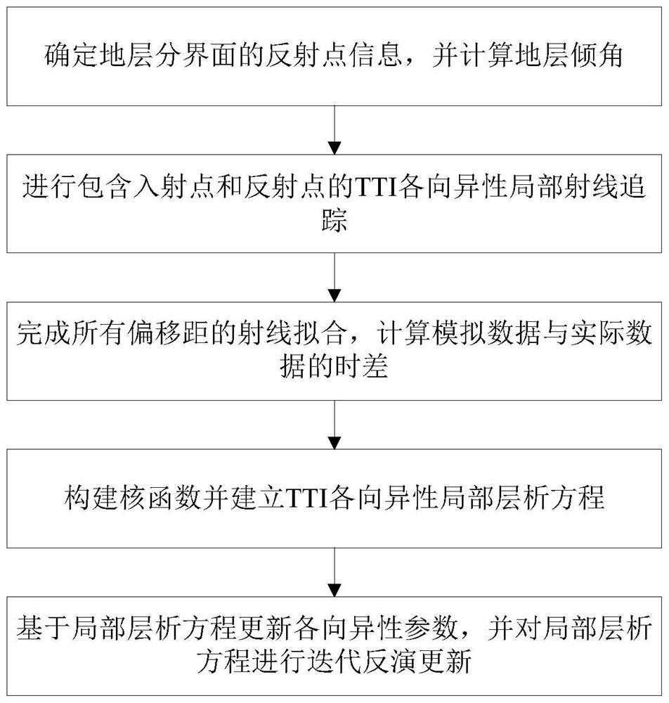
[0144] figure 1 A flowchart showing the steps of a TTI anisotropic local tomography method according to an exemplary embodiment of the present invention.

[0145] Such as figure 1 As shown, this embodiment proposes a TTI anisotropic local tomography method, the local tomography method includes:

[0146] Determine the reflection point information of the formation interface and calculate the formation dip;

[0147] Perform TTI anisotropic local ray tracing including incident and reflected points;

[0148] Complete the ray fitting of all offsets, and calculate the time difference between the simulated data and the actual data;

[0149] Construct the kernel function and establish the TTI anisotropic local tomographic equation;

[0150] The anisotropy parameters are updated based on the local tomographic equation, and the local tomographic equation is updated iteratively.

[0151] In this embodiment, a certain exploration area is taken as an example to carry out trial processi...


PUM


Abstract

The invention discloses a partial tomography method and system for TTI anisotropy. The partial tomography method for the TTI anisotropy comprises the steps that reflection point information of the interface of a formation is determined, and the inclination angle of the formation is calculated; TTI anisotropy local ray tracing including an incident point and a reflection point is carried out, the ray fitting of all offsets is completed, and the time difference between simulated data and actual data is calculated; a kernel function is constructed, and a TTI anisotropy local tomography equation is established; and anisotropy parameters are updated based on the local tomography equation, and iterative inversion update is carried out on the local tomography equation. The partial tomography method and system for the TTI anisotropy have the advantage that accurate logging stratification and seismic stratification data are used as constraint conditions, the geological structure of an established model is more realistic and reasonable; formation information extracted by logging data is very accurate, ray tracing is more effective, and a model numerical value is more accurate; and layer-by-layer inversion is adopted to enable the interval velocity of the model to be more realistic, more in line with the actual geological conditions, rather than an equivalent velocity model, and the partial tomography method and system for the TTI anisotropy can be more suitable as an initial model for tomography inversion.

Description

technical field [0001] The invention relates to the field of oil and gas exploration and development, and more specifically, to a TTI anisotropic local tomography method and system. Background technique [0002] There are extensive anisotropy characteristics in the subsurface formation medium, and the traditional isotropic seismic processing technology often leads to low imaging accuracy and even depth deviation. The application highlights the influence of anisotropy, and anisotropic seismic processing technology can solve many problems caused by isotropic processing. Anisotropic parameter modeling is the core key, and the generated anisotropic parameter model will directly affect the subsequent seismic processing effect. Therefore, the development of anisotropic parameter modeling technology has urgent practical significance. [0003] On the basis of investigating the detectable literature and patents at home and abroad, and understanding and researching the software produ...

Claims


Application Information

Patent Timeline
Patent Type & Authority Patents(China)
IPC IPC(8): G01V5/04G01V11/00
CPCG01V5/04G01V11/00
Inventor 郭恺王鹏燕
Owner CHINA PETROLEUM & CHEM CORP
Learn More