
Magnetic control type inter-platform basin drainer

A basin drain, magnetic control technology, applied in the field of bathroom, can solve problems such as water leakage

Inactive Publication Date: 2019-04-09
马荣昌
View PDF7 Cites 1 Cited by
  • Summary
  • Abstract
  • Description
  • Claims
  • Application Information

AI Technical Summary

Problems solved by technology

But at present this kind of mechanism needs to offer transverse through-hole in the pipe wall of downpipe, so that the connecting rod drawn by the pull rod stretches into downpipe, just can only be used as seal by a sphere in this throughhole, makes its tightness like this there is inherent Defects, a little longer time, there will always be obvious water leakage

Method used


Image

  • Magnetic control type inter-platform basin drainer
  • Magnetic control type inter-platform basin drainer
  • Magnetic control type inter-platform basin drainer

Examples


Embodiment 1

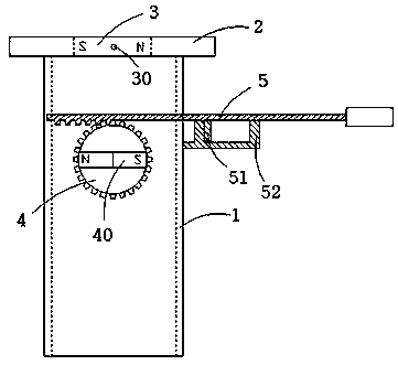
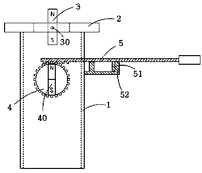
[0017] Such as figure 1 , figure 2 As shown, the magnetically controlled basin drain includes a sewer pipe 1; the top of the sewer pipe 1 is provided with an annular base 2 embedded in the through hole at the bottom of the basin, and a rotating basin plug 3 is matched in the annular base 2 , the rotating basin plug 3 is connected to the annular base 2 through a horizontally arranged spring shaft 30; Magnetization; the outside of the sewer pipe 1 is provided with a turntable 4 that can rotate in a vertical plane, and the turntable 4 is provided with a permanent magnetic strip 40 extending along the diameter of the turntable 4; the turntable 4 is coupled to a pull rod 5 , when the pull rod 5 is stretched outward to the outer limit position, the turntable 4 rotates to the first limit angle, at this time, the permanent magnetic strip 40 on the turntable 4 is in a vertical state, and the rotating basin The plug 3 is attracted to the vertical state, so that the basin is in the dr...

Embodiment 2

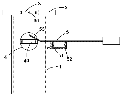
[0023] Such as image 3 As shown, the difference between the second embodiment and the first embodiment is that the coupling mode between the turntable 4 and the pull rod 5 is different; in the second embodiment, a connecting rod 53 is pivotally connected to the inner end of the pull rod 5, and the connecting rod 53 The other end of the other end is pivotally connected to an eccentric shaft fixed on the turntable 4 , so that the connection between the turntable 4 and the pull rod 5 is realized through the connecting rod 53 .


PUM


Abstract

The invention provides a magnetic control type inter-platform basin drainer. A ring-shaped base embedded in a through hole in the bottom of an inter-platform basin is arranged at the top of a sewer line; a rotary basin plug is arranged in the ring-shaped base and is connected with the ring-shaped base through a horizontally arranged spring shaft; the rotary basin plug is a permanent magnet and ismagnetized along the radial direction orthogonal to the spring shaft; a turnplate capable of rotating in the vertical plane is arranged outside the sewer line; a permanent magnetic strip extending along the diameter of the turnplate is arranged on the turnplate; the turnplate is coupled with one pull rod; when the pull rod is stretched to an outer limit position, the turnplate rotates to enable the permanent magnetic strip to be vertical and attracts the rotary basin plug to be vertical to enable the inter-platform basin in a water discharging state; and when the pull rod is inwards pushed toan inner limit position, the turnplate rotates to enable the permanent magnetic strip to be horizontal and removes attraction to the rotary basin plug, and the rotary basin plug recovers to the horizontal state and plugs the ring-shaped base to enable the inter-platform basin to be in a water accommodating state. The drainer can open and close the basin plug without using hands to stretch into thebottom of the inter-platform basin, and has high sealing property.

Description

technical field [0001] The invention relates to the field of sanitary ware, in particular to a basin drainer. Background technique [0002] In daily life, there will be sewage in the bathroom basin after use; and the current basin drains include flip-type drains, elastic push-type drains, and pull-type drains. For the first two kinds of drainers, it is necessary to reach into the bottom of the basin to open the basin plug, which is very inconvenient when the water body in the basin is dirty. [0003] However, for the current pull-type drain, it can be pulled by an external pull rod to make the plug of the drain rise or fall, thereby controlling the opening and closing of the drain; in this way, there is no need to directly touch the plug of the drain with your hands, and your hands will not be dirty. department. But at present this kind of mechanism needs to offer transverse through-hole in the pipe wall of downpipe, so that the connecting rod drawn by the pull rod stretch...

Claims


Application Information

Patent Timeline
IPC IPC(8): E03C1/22E03C1/23
CPCE03C1/22E03C1/2302E03C2001/2311
Inventor 马荣昌
Owner 马荣昌
Learn More