Automatic handcuffs arresting device

A handcuff and automatic technology, applied in handcuffs, building locks, buildings, etc., can solve the problem of not being able to prevent thieves from escaping from the scene, and achieve the effect of compact and reasonable structural design and high reliability

Active Publication Date: 2019-04-19
湖南创世智能科技有限公司
View PDF3 Cites 1 Cited by
  • Summary
  • Abstract
  • Description
  • Claims
  • Application Information

AI Technical Summary

Problems solved by technology

[0002] It is particularly important to do a good job in the anti-theft of safes, vault doors, tail cabinets, anti-theft doors, etc. in the financial industry, as well as military and police gun cabinets. At present, the anti-theft methods are mainly to install anti-theft doors and anti-theft locks. It is made of thicker metal material and has better anti-destructive performance. The anti-theft lock can resist abnormal opening under certain conditions within a certain period of time. With the advancement of technology, anti-theft needs to replace traditional mechanical In addition to the lock, it is also combined with an intelligent system, which can realize functions such as networked alarm, video surveillance and remote control. However, the above anti-theft measures can only prevent thieves from destroying the door and lock or sending out alarm messages to a certain extent, and cannot prevent thieves from escaping. on site

Method used


Image

  • Automatic handcuffs arresting device
  • Automatic handcuffs arresting device
  • Automatic handcuffs arresting device

Examples


Embodiment Construction

[0022] In order to facilitate the understanding of the present invention, the present invention will be described more fully and in detail below in conjunction with the accompanying drawings and preferred embodiments, but the protection scope of the present invention is not limited to the following specific embodiments.

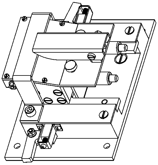
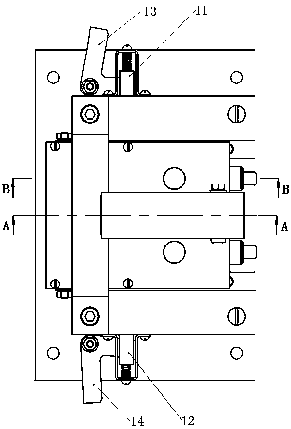
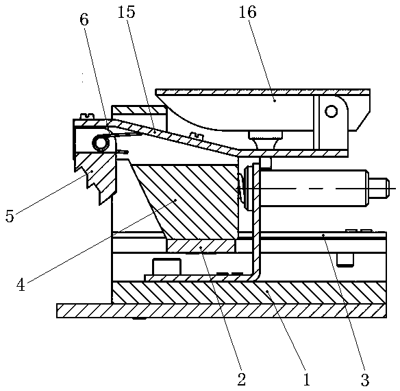
[0023] like Figure 1-Figure 7 As shown, an automatic handcuff arresting device in this embodiment includes a door panel, an opening is provided on the door panel, a clasp is provided inwardly at the opening, and a catch assembly is installed on the inner wall of the door panel near the back of the clasp hand , the catching assembly includes a base 1, the cross-section of the base is U-shaped, a step portion 102 is provided on the opposite side of the two side plates 101 of the base, and a tooth is placed on the horizontal step surface of the step portion 102 Plate 2, the tooth plate is U-shaped, including two parallel wing plates and an end plate connecting ...


PUM


Abstract

The invention discloses an automatic handcuffs arresting device. The automatic handcuffs arresting device comprises a door plate, wherein an opening is formed in the door plate, a buckle is inwards arranged in the opening, and a capturing assembly is installed on one side, close to the hand back, of the inner wall of the door plate; and the capturing assembly comprises a base, a toothed plate capable of moving back and forth along the base is arranged on the base, a connecting block is fixed at one end, close to the buckle, of the toothed plate, the front end of the connecting block is provided with a catching claw, a right-angled bent plate is fixed in the middle of the base, a shaft sleeve is arranged on the right-angled bent plate, the shaft core penetrates through the shaft sleeve andextends into the connecting block, a compression spring is arranged on the shaft core, one side of the toothed plate is provided with a triggering mechanism, and the other side of the toothed plate isprovided with a stepping mechanism. According to the automatic handcuffs arresting device, the triggering mechanism is used for triggering the compression spring to release, the toothed plate drivesthe connecting block and the catching claw to be quickly popped out, the fingers of a door opener can be automatically locked, the stepping mechanism can prevent fingers from struggling, the arrestingfunction is achieved, and the device can be applied to safe cases, safety doors, tail box cabinets, anti-theft doors in the financial industry, military and police firearm cabinets and the like.

Description

technical field [0001] The invention relates to the technical field of security devices, in particular to an automatic handcuff arresting device. Background technique [0002] It is particularly important to do a good job in the anti-theft of safes, vault doors, tail cabinets, anti-theft doors, etc. in the financial industry, as well as military and police gun cabinets. At present, the anti-theft methods are mainly to install anti-theft doors and anti-theft locks. It is made of thicker metal material and has better anti-destructive performance. The anti-theft lock can resist abnormal opening under certain conditions within a certain period of time. With the advancement of technology, anti-theft needs to replace traditional mechanical In addition to the lock, it is also combined with an intelligent system, which can realize functions such as networked alarm, video surveillance and remote control. However, the above anti-theft measures can only prevent thieves from destroying ...

Claims


Application Information

Patent Timeline
Patent Type & Authority Applications(China)
IPC IPC(8): E05B75/00
CPCE05B75/00
Inventor 杨社成
Owner 湖南创世智能科技有限公司
Why Eureka
Try Eureka