Defrosting control method and system for heat pump system

A technology of a heat pump system and a control method, which is applied in the direction of refrigerators, refrigeration components, refrigeration and liquefaction, etc., can solve problems such as affecting heating efficiency, unclean defrosting, and reduced air circulation, so as to ensure the defrosting effect and improve the system efficiency. The effect of thermal efficiency

Active Publication Date: 2019-04-19
GUANGDONG PHNIX ECO ENERGY SOLUTION
View PDF5 Cites 8 Cited by
  • Summary
  • Abstract
  • Description
  • Claims
  • Application Information

AI Technical Summary

Problems solved by technology

[0002] When the heat pump system is heating, when the ambient temperature is lower than the freezing point, the water vapor in the air will condense into a frost layer on the surface of the heat exchanger. The frost layer not only directly increases the heat transfer resistance of the heat exchanger, but also makes it pass through Reduced air flow through the heat exchanger, resulting in less efficient heat transfer, necessitating action to defrost
[0003] In the past, heat pumps generally adopted the following defrosting logic: when the defrosting condition is reached, defrosting is started, after the defrosting is completed, the heating is performed for a fixed time, and after the fixed time heating is completed, it is detected whether the surface temperature of the fin heat exchanger has reached the defrosting level. When the condition is reached, it will enter defrosting, and if it is not reached, it will continue to heat. Such a defrosting logic, because the heating time is fixed, will cause unclean defrosting due to special circumstances or special working conditions, which will affect the heating efficiency.

Method used


Image

  • Defrosting control method and system for heat pump system
  • Defrosting control method and system for heat pump system
  • Defrosting control method and system for heat pump system

Examples


Embodiment Construction

[0056] The implementation of the present invention is described below through specific examples and in conjunction with the accompanying drawings, and those skilled in the art can easily understand other advantages and effects of the present invention from the content disclosed in this specification. The present invention can also be implemented or applied through other different specific examples, and various modifications and changes can be made to the details in this specification based on different viewpoints and applications without departing from the spirit of the present invention.

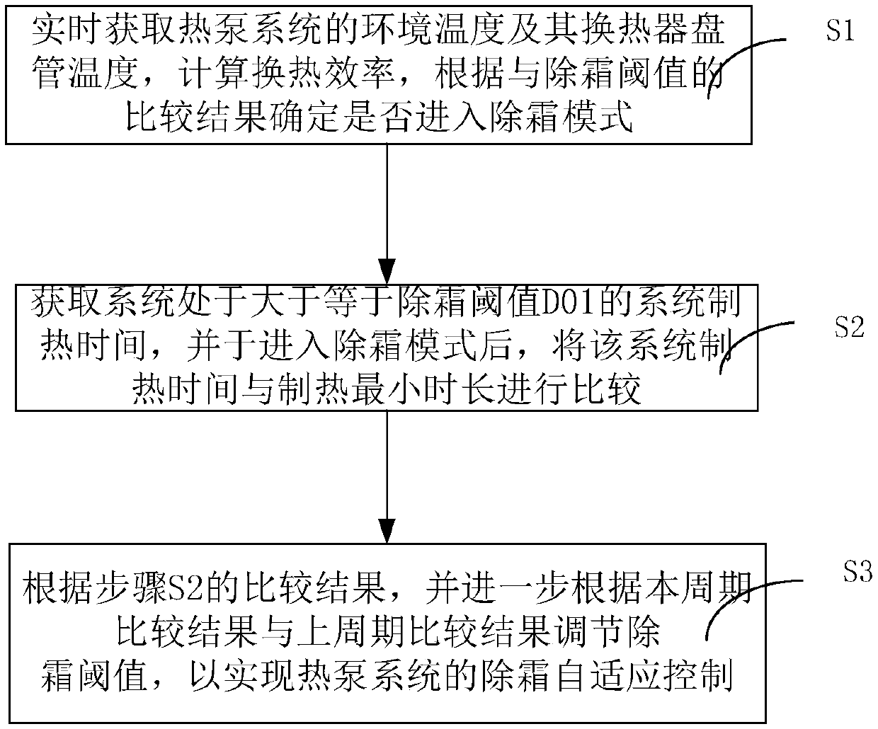
[0057] figure 1 It is a flowchart of steps of a defrosting control method for a heat pump system in the present invention. Such as figure 1 As shown, a defrosting control method for a heat pump system of the present invention includes the following steps:

[0058] Step S1, obtain the ambient temperature T of the heat pump system in real time 环境温度 and its heat exchanger coil temperature T...


PUM


Abstract

The invention discloses a defrosting control method and system for a heat pump system. The method comprises the following steps that S1, the environment temperature T-environment temperature of the heat pump system and the heat exchanger coil temperature T-heat exchange of the heat pump system are obtained in real time, the heat exchange efficiency delta T-heat exchange efficiency is calculated, and whether a defrosting mode is started or not is determined according to the comparison result of the delta T-heat exchange efficiency and a defrosting threshold value; S2, the system heating time when the system is larger than or equal to the defrosting threshold value D01 is obtained, and after the defrosting mode is started, the time is compared with the minimum heating duration; and S3, according to the comparison result obtained in the step 2, the defrosting threshold value is further adjusted according to the comparison result of the period and the comparison result of the last period so that the defrosting self-adaptive control of the heat pump system can be realized. According to the defrosting control method and system, the defrosting time and the heating duration are judged comprehensively, so that the heating duration is adjusted, and then the defrosting effect is guaranteed.

Description

technical field [0001] The invention relates to the technical field of heat pump control, in particular to an adaptive defrosting control method and system for a heat pump system. Background technique [0002] When the heat pump system is heating, when the ambient temperature is lower than the freezing point, the water vapor in the air will condense into a frost layer on the surface of the heat exchanger. The frost layer not only directly increases the heat transfer resistance of the heat exchanger, but also makes it pass through Reduced air flow through the heat exchanger results in a less efficient heat exchange, so measures need to be taken to defrost. [0003] In the past, heat pumps generally used the following defrosting logic: when the defrosting condition is reached, defrosting is started, after the defrosting is completed, the heating is performed for a fixed time, and after the fixed time heating is completed, it is detected whether the surface temperature of the f...

Claims


Application Information

Patent Timeline
IPC IPC(8): F25B47/00F25B49/02
CPCF25B47/00F25B49/02F25B2600/01
Inventor 雷朋飞黄世哲叶景发刘远辉高翔刘辉吴思朗吴东华朱晓广廖立元刘志力梁华锋冯利伟
Owner GUANGDONG PHNIX ECO ENERGY SOLUTION
Why Eureka
Try Eureka