
A dual-fuel direct injection injector for vehicles

A dual-fuel and fuel injector technology, applied in fuel injection devices, charging systems, machines/engines, etc., can solve problems such as increased cost, increased control difficulty, and limited layout space

Active Publication Date: 2021-05-11
TONGJI UNIV
View PDF6 Cites 0 Cited by
  • Summary
  • Abstract
  • Description
  • Claims
  • Application Information

AI Technical Summary

Problems solved by technology

However, the fixed fuel mixing ratio cannot meet the most efficient combustion of the engine under all load conditions, especially when the ethanol evaporates and absorbs heat during cold start and low temperature operation, which affects the engine performance. Water will be stratified, so dehydration treatment is required in the production of ethanol, resulting in additional energy consumption and cost, as well as high requirements for the storage environment and short shelf life (4-5 days). This instability causes engine fuel Increased buildup on the intake system negatively affects combustion efficiency
Another way is to combine intake port injection and in-cylinder direct injection, injecting ethanol and other highly volatile fuels in the intake port, and directly injecting gasoline and other fuels in the cylinder. This method requires two sets of electronically controlled fuel supply systems , making the engine structure complex, increasing the difficulty of control, and injecting highly volatile fuel in the intake port directly affects the charge coefficient of the engine, and affects the combustion and emission of the engine
In addition, as disclosed in the Chinese patent application number 201710288158.7, the combustion control method of the dual-fuel-dual direct injection internal combustion engine arranges two injectors for controlling the injection of two fuels on the cylinder head, and the nozzles of the injectors are located in the combustion chamber Internally, in-cylinder direct injection and coordinated stratified combustion of different active fuels (such as low activity fuels represented by gasoline and alcohol fuels and high activity fuels represented by diesel and dimethyl ether) are realized, but this method requires two Injectors, which add cost and are limited by the limited layout space of the cylinder head

Method used


Image

  • A dual-fuel direct injection injector for vehicles
  • A dual-fuel direct injection injector for vehicles

Examples


Embodiment

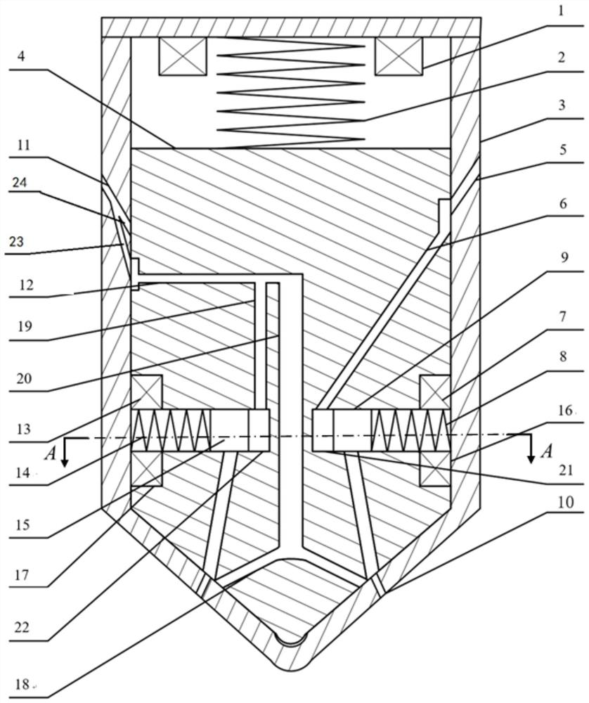
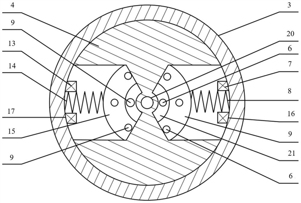
[0037] A dual-fuel direct injection fuel injector for vehicles, such as Figure 1-2 shown, including:

[0038]The injector body 3, and the main valve core 4 which is arranged inside the injector body 3 and can move up and down along the axis of the injector body 3; the first fuel inlet 5 is located at one side of the upper part of the injector body 3, and the second fuel inlet 11 is located at On the other side opposite to the upper part of the injector body 3, its end is branched up and down in a Y shape; the injection hole 10 is located at the bottom of the injector body 3; the first fuel passage 6 and the second fuel passage are arranged inside the main valve core 4, respectively One side of the first fuel inlet 5 and the second fuel inlet 11, the second fuel passage is divided into a second fuel passage front section 12 and a second fuel passage rear section 19, and the second fuel passage front section 12 leads out from the second fuel passage rear section. 19 parallel s...


PUM


Abstract

The invention relates to a dual-fuel direct injection fuel injector for vehicles, comprising an injector body (3) and a main valve core (4) arranged inside the injector body (3) and moving up and down along its axis. A first fuel passage assembly and a second fuel passage assembly are arranged inside the spool (4), and the ends of the first fuel passage assembly and the second fuel passage assembly are connected to the nozzles arranged on the injector body (3). The holes (10) are connected. Compared with the prior art, the present invention utilizes one fuel injector to realize dual-fuel injection, thereby realizing dual-fuel mixed combustion, mixed gas stratification, etc. The injection mode expands the operating conditions of the GDI engine, saves space, and is conveniently arranged on the cylinder head to meet the requirements of engine miniaturization and intensification.

Description

technical field [0001] The invention relates to a fuel injector, in particular to a dual-fuel direct injection fuel injector for vehicles. Background technique [0002] The rapid development of the automobile industry and the continuous increase in the number of automobiles not only provide convenience for people's daily life, but also cause increasingly serious energy and environmental problems. Therefore, the internal combustion engine is currently the main power plant of automobiles, and energy saving and emission reduction is the theme of its development. In order to realize the lean stratified combustion of the engine, and then improve the thermal efficiency, improve the power economy and reduce the emission, the in-cylinder direct injection technology is introduced. On the other hand, in order to get rid of the dependence on traditional fossil energy, the possibility of clean energy such as alcohol fuel and biodiesel as alternative fuel is also being extensively studi...

Claims


Application Information

Patent Timeline
Patent Type & Authority Patents(China)
IPC IPC(8): F02M43/04F02M51/06
CPCF02M43/04F02M51/061
Inventor 石秀勇廖延苏倪计民康杨刘强周雷
Owner TONGJI UNIV
Learn More