
Secondary mirror assembly capable of reducing obscuration ratio

A technology of obscuration ratio and secondary mirror, applied in optical components, installation, optics, etc., can solve the problem of destroying the plane structure of the back of the secondary mirror, and achieve the effect of easy installation, stable and reliable overall structure, and easy processing.

Active Publication Date: 2019-04-26
CHANGCHUN INST OF OPTICS FINE MECHANICS & PHYSICS CHINESE ACAD OF SCI
View PDF6 Cites 1 Cited by
  • Summary
  • Abstract
  • Description
  • Claims
  • Application Information

AI Technical Summary

Problems solved by technology

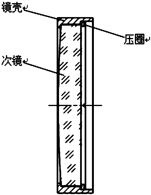
To solve this problem, the back support scheme can also be adopted, that is, three cylindrical holes are opened on the back of the mirror, and the secondary mirror is fixed through flexible joint connections; or a circular boss is processed in the center of the back of the secondary mirror, and supported by bonding ; but the existing back support scheme needs to be processed on the back of the secondary mirror, which destroys the plane structure of the back of the secondary mirror

Method used


Image

  • Secondary mirror assembly capable of reducing obscuration ratio
  • Secondary mirror assembly capable of reducing obscuration ratio
  • Secondary mirror assembly capable of reducing obscuration ratio

Examples


Embodiment Construction

[0011] The following will clearly and completely describe the technical solutions in the embodiments of the present invention with reference to the accompanying drawings in the embodiments of the present invention. Obviously, the described embodiments are only some, not all, embodiments of the present invention. Based on the embodiments of the present invention, all other embodiments obtained by persons of ordinary skill in the art without making creative efforts belong to the protection scope of the present invention.

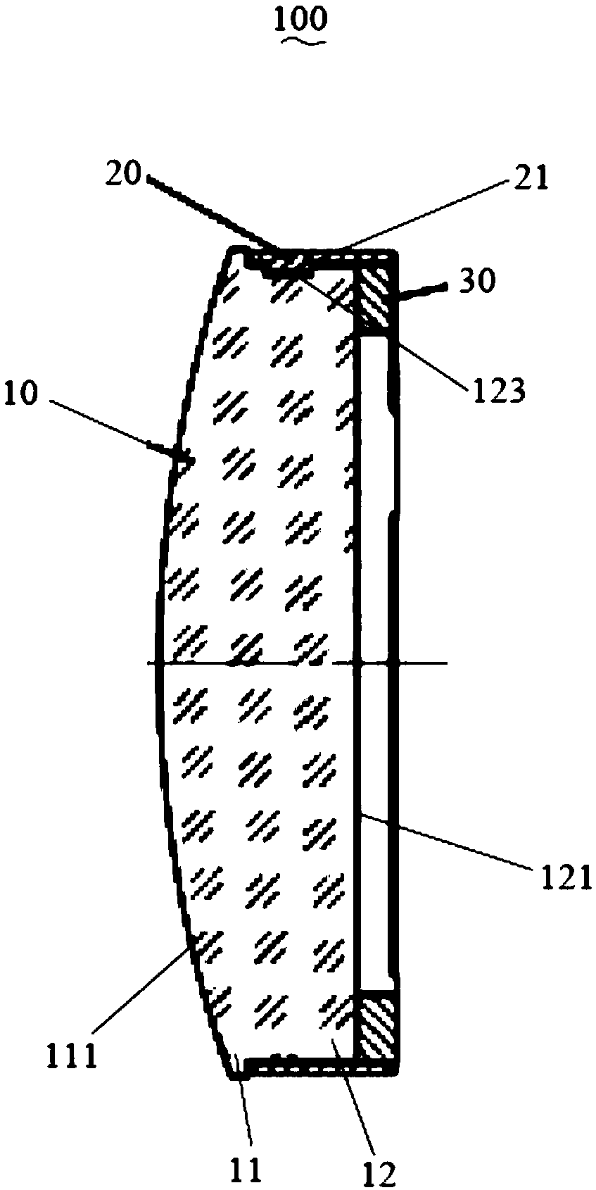
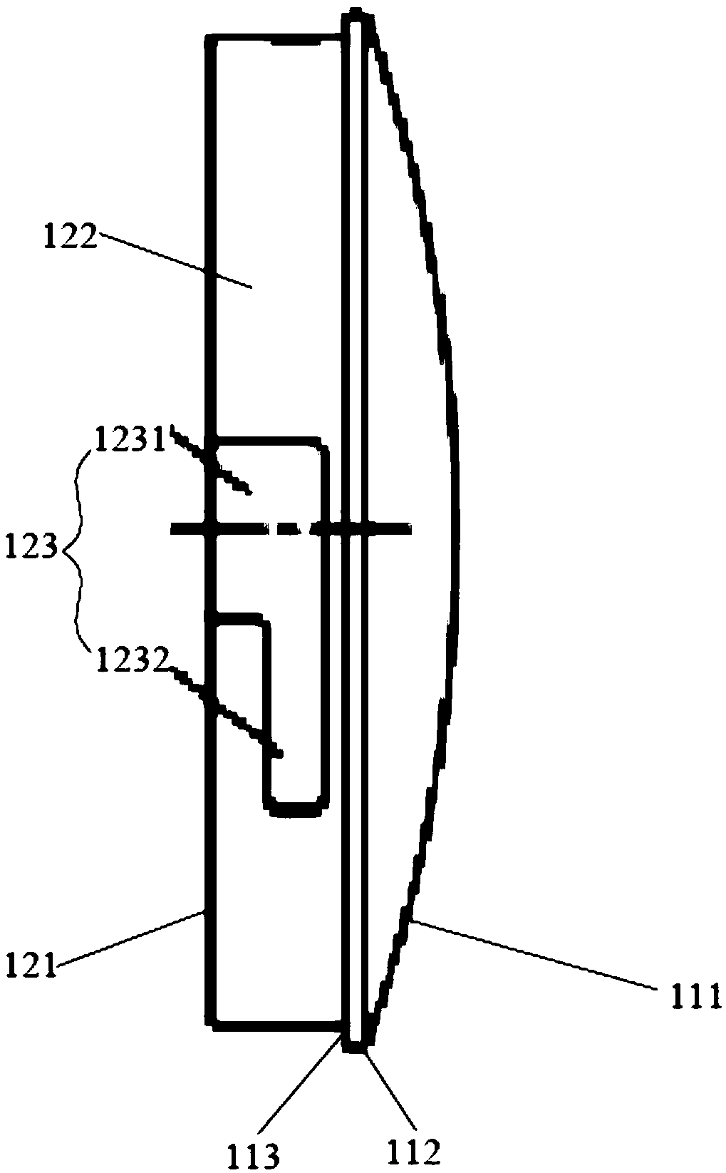
[0012] see Figure 2 to Figure 4 , a secondary mirror assembly 100 that reduces the obscuration ratio provided by the present invention includes a secondary mirror 10, a mirror housing 20 and a pressure ring 30, and the secondary mirror 10 includes a front end 11 and a rear end 12 connected to one side of the front end 11 The front end 11 is a structure of revolution and includes a first optical surface 111; the rear end 12 is a cylinder and coaxially arranged...


PUM


Abstract

The invention discloses a secondary mirror assembly capable of reducing the obscuration ratio. The secondary mirror assembly comprises a secondary mirror, a mirror shell and a pressing ring, the secondary mirror comprises a front end and a back end connected with one side of the front end; the front end is of a revolution body structure and comprises a first optical surface; the back end is a cylinder, the back end and the front section are coaxially arranged, the diameter of the back end is smaller than that of the front end, and the back end comprises a second optical surface back on to thefirst optical surface and a cylindrical side surface connected with the second optical surface and the front end; the cylindrical side surface is concave to form two locating grooves; the mirror shellis in a hollow cylindrical shape, and the inner diameter of the mirror shell corresponds to the diameter of the back end, and locating bosses corresponding to the locating grooves one to one protrudefrom the inner surface of the mirror shell and extend; the mirror shell sleeves the back end of the secondary mirror, one end of the mirror shell is opposite to the front end of the secondary mirrorat an interval, and all the locating bosses are stored in the locating grooves; the pressing ring is in an annular shape with the outer diameter corresponding to the inner diameter of the mirror shell, and the pressing ring is stored in the mirror shell and abuts against the second optical surface. According to the secondary mirror assembly, the center obscuration ratio is reduced to be minimum, and the secondary mirror assembly is stable and reliable in whole structure, and easy to process, install and adjust.

Description

technical field [0001] The invention relates to the technical field of secondary mirrors applied to coaxial optical systems such as coaxial telescopic systems and camera systems, in particular to a secondary mirror assembly that reduces the blocking ratio. Background technique [0002] A coaxial optical system generally includes a primary mirror assembly and a secondary mirror assembly coaxial with the primary mirror assembly. The coaxial optical system has a greater competitive advantage due to its simple structure, stability and reliability, and easy assembly and adjustment. However, the secondary mirror assembly Central obscuration has always been an inevitable defect of coaxial optical systems, so how to minimize the obscuration ratio is a difficult point that designers in coaxial systems have been exploring and striving to overcome. Improvements to the support structure for the secondary mirror are included in the many existing exploration proposals. Since the typical ...

Claims


Application Information

Patent Timeline
Patent Type & Authority Applications(China)
IPC IPC(8): G02B7/02
CPCG02B7/02G02B7/026
Inventor 郭疆李元鹏朱磊齐洪宇龚大鹏王浩
Owner CHANGCHUN INST OF OPTICS FINE MECHANICS & PHYSICS CHINESE ACAD OF SCI
Learn More