An antenna leveling method and system

An antenna platform and antenna technology, used in radio wave measurement systems, antenna radiation patterns, instruments, etc., can solve problems such as antenna linear scanning track sinking, achieve constant radiation gain, and optimize measurement data.

Active Publication Date: 2021-05-25
BEIJING INST OF ENVIRONMENTAL FEATURES
View PDF0 Cites 0 Cited by
  • Summary
  • Abstract
  • Description
  • Claims
  • Application Information

AI Technical Summary

Problems solved by technology

The following problems were found during the test: First, due to the heavy weight of the front of the antenna platform (that is, the platform on which the antenna is installed), the end of the antenna linearly scanning the track sank

Method used


Image

  • An antenna leveling method and system
  • An antenna leveling method and system
  • An antenna leveling method and system

Examples


Embodiment Construction

[0023]In order to make the objects, technical solutions, and advantages of the present invention more clearly, the technical solutions in the embodiments of the present invention will be described in contemplation in the embodiments of the present invention, and will be described, and the embodiments described in the embodiments of the present invention will be described. It is a part of the embodiments of the invention, not all of the embodiments. Based on the embodiments of the present invention, all other embodiments obtained by those of ordinary skill in the art without making creative labor are the scope of the present invention.

[0024]image 3 It is a schematic diagram of an antenna leveling system according to an embodiment of the present invention. Such asimage 3 As shown, the antenna leveling system of the embodiment of the present invention may include at least three ranging units, and each speed length can be directed at the edge of the antenna platform at the edge of the a...


PUM


Abstract

The present invention relates to an antenna leveling method and system. An embodiment of the system includes: at least three distance measuring units; each distance measuring unit in the at least three distance measuring units is arranged on the edge of the bottom surface of the antenna platform , the signal transmission direction of each ranging unit points to the ground; wherein, each ranging unit is used to obtain the distance between it and the ground; the distance obtained by the at least three ranging units is used for comparison: in the comparison result If they are the same, it means that the scanning surface of the antenna is parallel to the ground; if the comparison result is different, adjust the attitude of the antenna until the comparison result is the same. This embodiment can use the distance measuring unit to realize antenna leveling, and solve the problem of different radiation gains received by the target due to the different heights at the beginning and end of antenna scanning in the existing near-field electromagnetic test.

Description

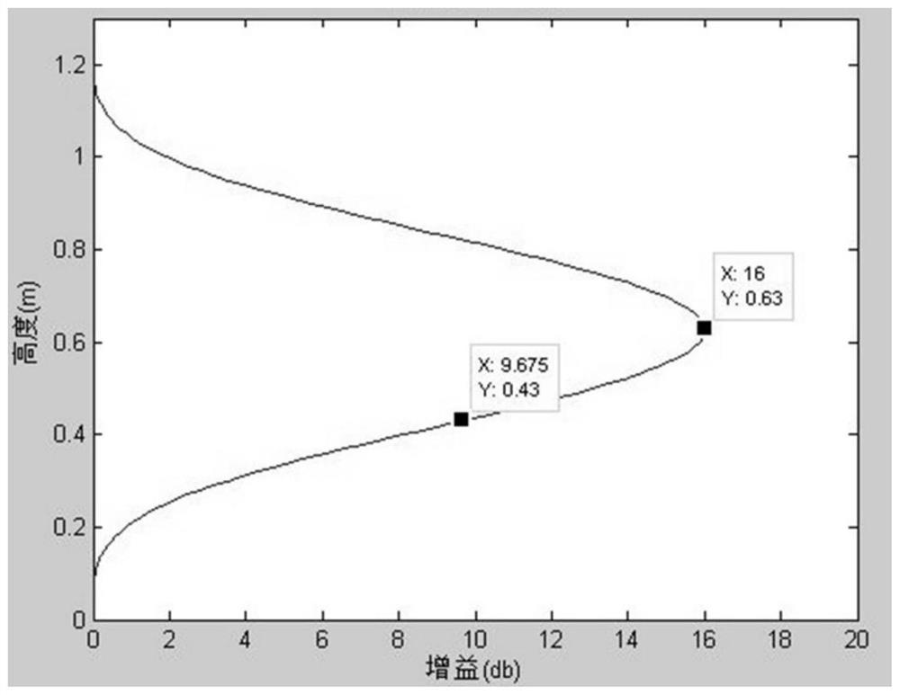
Technical field[0001]The present invention relates to the field of antenna, in particular, to an antenna leveling method and system.Background technique[0002]The near field electromagnetic measurement system belongs to the in-vehicle measurement system, the measurement method is an antenna to move scan targets in approximate horizontal movement. Electromagnetic waves are spoon distribution in the radiation gain in the vertical surface direction in the target.figure 1 The antenna radiation gain varies from the height (i.e., the distance between the antenna and the ground) (the abscissa is a radiation gain, the ordinate is height), it can be seen that the height difference is 0.2m, the gain difference can reach 6.325dB, visible antenna height Differences can result in different measurement data in different radiation gains. The following problems were found during the test: First, due to the one end of the frontline scan track of the frontline of the antenna platform (i.e., the platfo...

Claims


Application Information

Patent Timeline
Patent Type & Authority Patents(China)
IPC IPC(8): G01R29/10G01S15/08G01S17/08
CPCG01R29/10G01S15/08G01S17/08
Inventor 候浩浩高超吕鸣刘芳李常志
Owner BEIJING INST OF ENVIRONMENTAL FEATURES
Why Eureka
Try Eureka